Eikonal Distributions in Two-Mirror Imaging Systems
Vadim A. Kaloshin, Alexander S. Venetskiy
Kotel’nikov Institute of Radio-engineering and Electronics of RAS
Received March 19, 2013
Abstract. Three terms of the eikonal distribution expansion in the aperture of a symmetric two-mirror imaging system in powers of a source transverse displacement from one of the foci have been obtained. The terms of the expansion are expressed through the mapping function and its derivative. The accuracy of the derived formula has been checked for the aplanatic two-mirror system.
Keywords: Geometric optics, mirror systems, eikonal aberrations.
Аннотация. Получены три члена разложения распределения эйконала в апертуре осесимметричного двухзеркального объектива по степеням поперечного смещения источника из фокуса. Члены разложения выражены через функцию отображения волновых фронтов и ее производную. Точность полученной формулы проверена для апланатической двухзеркальной системы.
Ключевые слова: геометрическая оптика, системы зеркал, аберрации эйконала.
Symmetric two-mirror systems have found wide applications in constructing of optical instruments. One can use the classical theory of ray aberrations based on an expansion in powers of an image displacements in analyzing and optimizing mirror systems [1]. This technique is very efficient in analyzing paraxial rays, but it needs taking into account high order aberrations for wide angle systems. An eikonal distribution in a mirror system aperture has a compact form and gives more information for analysis of the image quality. For example, we can use this distribution in analyzing diffraction effects. The eikonal distribution can be obtained by a ray-tracing technique, but it needs a large amount of calculations. Another way is to use a series of wave front aberrations [2], but complicated formulas are required to analyze and optimize wide angle systems. We can use the well-known formula for the two terms of the eikonal distribution expansion in powers of a source displacement from the focus [3]. However, its accuracy falls down sharply if the displacement increases. In addition, the formula does not describe the eikonal aberrations in aplanatic systems.
A formula that describes the first three terms of the expansion of the eikonal distribution in the aperture of a symmetric two-mirror telescopic system in powers of the source transverse displacement from the focus was derived in [4]. A formula that describes the first three terms of the expansion of the eikonal distribution in the aperture of a symmetric two-mirror telescopic system in powers of the source arbitrary displacement from the focus was derived in [5].
In this paper we derive the formula that describes the first three terms of the expansion of the eikonal distribution in the aperture of a symmetric two-mirror imaging system in powers of the source transverse displacement from one of the foci.
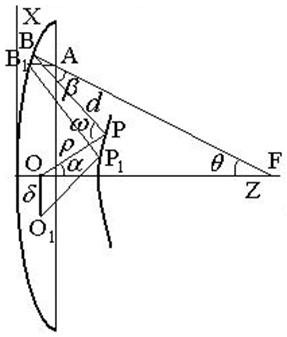
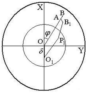
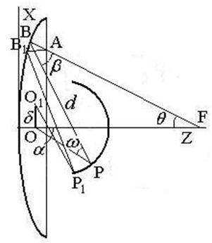
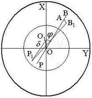
Let us consider two types of symmetric two-mirror systems with the point source displaced from the first focus O along the axis X of the Cartesian system of coordinates (see Figs. 1, 2). The first of them is the Cassegrain type and the second one is the Gregorian type.
If the source is located at the first focus O, the spherical front is formed in the primary mirror aperture with a center in the second focus F. Let us suppose that for any point A in the aperture with coordinates (rcosj, rsinj , zA) there is the only ray outgoing from the source at an angle α to the system axis Z and going through the point A and the point F at an angle q to the axis Z. The angles j, q, a are shown in Figs.1,2. So, there is a one-to-one correspondence between the angle q and the point A, and between the angle q and the angle α described by a mapping function
![]() (1)
(1)
(a) (b)
Fig. 1. A system of the first type:
(a) a projection in XZ plane, (b)- a projection in XY plane
(a) (b)
Fig. 2. A system of the second type:
(a)-a projection in XZ plane, (b)- a projection in XY plane
Let the point O1 be the position of the transversally displaced source along the axis X. We suppose that the one-to-one correspondence between aperture points and rays emerging from O1 is retained if the source is displaced to point O1. In this case, there is the only ray connecting the displaced source and the point A. The eikonal L along this ray is equal to the sum of three lengths:
![]() (2)
(2)
For the convenience of the subsequent manipulations let us choose the XYZ coordinate system with the center in the focal point O and the point A on the axis X with the coordinates (ХА, 0, ZA). The other points have the following coordinates: В(ХB, 0, ZB), B1(XB + ΔX, ΔY, ZB + ΔZ), P(xP, 0, zP), P1(xP + Δx, Δy, zP + Δz), O1(–δcosj, δsinj, 0), and O(0, 0, 0) where ZB =f(XB), zP = ψ(хP), Z = f(X) and z = ψ(x) are equations for the generatrices of the primary and secondary mirror, respectively.
We can present the expression (2) for the eikonal as
![]()
![]() (3)
(3)
![]()
Let us expand ΔZ and Δz in powers of Δx, Δy, ΔX and ΔY
 (4)
(4)
![]()
 (5)
(5)
The values Δx, Δy, ΔX and ΔY are unknowns. Having replaced ΔZ and Δz in the expression (3) with the expansions (4) and (5), having expanded the expression (3) for the eikonal in a power series of ΔX, ΔY, Δx, and Δy up to the terms of the third order and using the Fermat principle, one can obtain the system of linear equations for the unknowns ΔX, ΔY, Δx and Δy
![]() ;
; ![]() ;
; ![]() ;
;  (6)
(6)
Having found the values ΔX, ΔY, Δx and Δy from the system (6), having substituted them into Eq. (3) and retaining the terms of the first and the second power of δ, we obtain
 , (7)
, (7)
 , (8)
, (8)
 , (9)
, (9)
 ,
,  , (10)
 , (11)
 , (12)
where L0=r+d+t, r=÷OPê, d=÷BPê, t=÷ABê; (r,0)- polar coordinates of the point A, (d, p-j)- polar coordinates of the point O1 in the rotated Cartesian coordinate system; КВ and КР are the curvatures of the mirrors at the points В and Р; θ and ω are the angles between incident and reflected rays at these points, respectively.
Considering the ray geometry, we can express the formulas (10)–(12) through the mapping function q (a) and its derivative:
 ,
,  , (13)
 , (14)
 , (15)
where R=÷FBê. Using (13)–(15), we can reduce (8), (9) to
 , (16)
 (17)
(17)
where the upper and lower signs in (16), (17) refer to the two-mirror systems 1 and 2, respectively, t=R–(ZF–ZA)/cosq, , ZF is the coordinate of the point F, d=r0+d0+R0–r– R; r0, d0, R0 are the values of r, d, R on the axis Z; r can be expressed through α from the equation of the secondary mirror generatrix r= r (α), α can be expressed through q from (1), R also can be expressed through q from the equation of the primary mirror generatrix R= R(q), q =arctan[r/(ZF–ZA)]. So, R, q, α, r and t are expressed through r in formulas (16,17), and the formula (7) depends on the mapping function q(a), its derivative and the shape of the mirror generatrices. Using the results obtained in [5], the shape of the mirror generatrices can be expressed through the mapping function too.
Returning to the original XYZ coordinate system (see Figs. 1, 2), where the points O1 and A have polar coordinates (d, p) and (r,j), respectively, it is easy to show that the expression (7) is valid.
If a two-mirror system contains only second-order surfaces,
![]() (18)
(18)
and![]() . Therefore, the formula (7) is simplified:
. Therefore, the formula (7) is simplified:
 , (19)
where L2 is given by the formula (17).
If F® ¥, the formulas (7) and (19) turn to the corresponding ones obtained in [4, 5].
The accuracy of the derived formula (7) has been checked for the aplanatic two-mirror system of the first type as an example. The system has the following parameters: the primary and secondary mirror aperture diameters are D = 1 and Ds = 0. 5643, the angular apertures are N = 3.33333 and n = 0.88604, respectively, the distance between the mirrors d0 = 0.66666, the distance between the first focus O and the secondary mirror is r0=0.5, the distance between the primary mirror and the second focus F is R0=3.33333. The value of transverse displacement d=0.1. The mirrors generatrices are determined by formulas given in [6]:

 ,
,

 ,
,
where
![]() ,
, ![]() ,
, ![]() ,
, ![]() ,
, ![]() ,
, ![]() ,
, ![]() ,
, ![]() , M=0.30006,
, M=0.30006,
![]() .
.
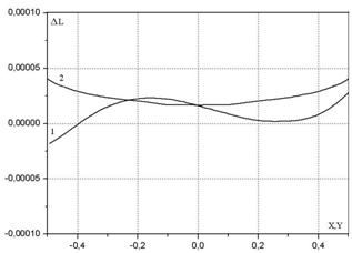
Fig. 3. The dependence of the formula (7) error upon coordinates.
The difference DL between the eikonal distributions in the aperture calculated from formula (7) and through the exact ray-tracing calculation for the source transverse displacement δ = 0.1 along the axis X is shown on Fig.3 by curve 1 (for the distribution along X axis) and by curve 2 (for the distribution along Y axis). One can see that the maximum error of the formula (7) is 4 ×10⁻⁵.
It should be noted that the formula (7) might be used not only for calculations. Also, it can be useful for analytical optimizing a two-mirror imaging system.
The technique developed in this paper might be used to obtain the third and next terms of the eikonal distribution expansion in powers of the source transverse displacement. Also, it is possible to obtain an eikonal distribution formula for a multiple mirror system.
1. T. T. Saha, “Transverse ray aberrations for paraboloid-hyperboloid telescopes,” Appl. Opt. 1985, 24, pp.1856-1863.
2. A. Gomez-Vieyra and D. Malacara-Hernández, “Geometric theory of wavefront aberrations in an off-axis spherical mirror,” 2011, Appl. Opt. 50, pp.66-73.
3. M. Born and E. Wolf, Principles of Optics, Pergamon, Oxford, 1968.
4. A. S. Venetskiy, V. A. Kaloshin, “On the Theory of Two-Mirror Telescopic Systems,” 2010, Doklady Physics,Vol 55, No.9, pp. 427–430.
5. A. S. Venetskiy, V. A. Kaloshin, “ On Eikonal Distribution in the Aperture of a Two_Mirror Telescopic System”, Journal of Communications Technology and Electronics, 2012, Vol. 57, No. 9, pp. 1004–1011.
6. A. K. Head, “The two-mirror aplanat,” Proc. Phys. Soc., 1957, B, 70, pp. 945-949.