|
|
"ЖУРНАЛ РАДИОЭЛЕКТРОНИКИ" N 5, 2004 |
|


Precise laser interferometry with 1 pm resolution
M. N. Dubrov and V. A. Alyoshin
Institute of Radioengineering and Electronics, Russian Academy of Sciences,
Vvedensky sq. 1, Fryazino, Moscow Region 141190, Russia
Submitted May 05, 2004
II. Precise laser interferometry problem
III. Interferometer servo-system
IV. Precise laser interferometry application
I. Introduction
The progress in nano-technology (nanoelectronics, nano-machines) and precise physical measurements initiate a permanent growth of the optical interferometry instrumentation accuracy. The development of heterodyne Michelson interferometer with 10 picometer resolution has been recently reported[1]. The most of precise interferometer applications require a high accuracy of these instruments to be ensured in a wide frequency and dynamic ranges. The circumstance is important because of a few order more sensitive, than the reported in [1], narrow range laser tools have been already tested in previous decades [2,3].
In this paper we represent the distinguished laser interferometer technique that allows the wide sort of precise object displacements to be measured with the instrumental resolution up to 1 pm. The interferometer readout accuracy keeps this level in the range of the interference fringe displacements beyond the ±105 periods (±2p x105 radians); the frequency band of 10-5 Hz - 1 kHz has been realized. The laser interferometry techniques, which are used in our optical-electronic device, are based on a especial measuring methods and some control and tuning features.
II. Precise laser interferometry problem
There are two basic problems when any interference pattern shifts have to be measured with a high accuracy. The first one is to avoid or to eliminate the output power and frequency fluctuations of the light source. (If even the frequency stabilized laser is used its output is not stable enough to achieve the quantum limit in a measure of interference fringe displacements). The second problem occurs when the high resolution and linearity of records in the whole measure range of phase shifts d including the points of irregular transit (d = +180° / -180° or d = 0° / 360° circular phase shift) are needed.
As early as in 1970s we introduced for a solution of these problems the modernized servo-system which was earlier used by V. Valy in his long-path interferometer instruments [4]. The principle of operation of this new distinguished system prototype[5] and its basic arrangements have been already discussed in the number of our publications [6-10]. In this paper we summarize our recent progress in the interferometer servo-system developments, its up-grade, and investigations.
III. Interferometer servo-system
A. Design and operation
The block-diagram of servo-system is shown in Fig.1. The interference pattern (e.g. pattern from a two-arm Michelson interferometer) is focused onto the mirror of the electric-mechanical deflector. The coming back pattern is displayed at the transparent-reflecting grating (TRG). It is fabricated by coating the reflecting thin film fringes onto the transparent glass substrate. The fringes of this grating are parallel to the fringes of the initial interference pattern, and their periods coincide.
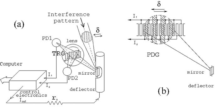
Fig.1. Schematic diagram of precise interferometer servo-system based on the transparent-reflecting grating TRG (a), and the photo-diode grating PDG (b). The output signal Uout = Iout x r0 is stored at computer, digital data logger, or any analogue recorder.
The convex lens being inserted in front of grating TRG condenses the two parts of light flows - one, which is passed through the grating, and another, which is reflected from the grating - at two photo-detectors: PD1 and PD2 respectively. These detectors are connected to the inputs of the differential direct-current amplifier that is included into the electronic control unit. The output current of this unit can turn the mirror of the deflector. Thus the feedback loop of our servo-system is locked. As soon as the fringes of the interference pattern are shifted by any cause, then the image, which is displayed on the grating TRG, is forced to be moved along the TRG, so that both the flows of light at the photo-detectors PD1, PD2, and respectively the input currents I1 , I2 incoming to the control electronics would be equal: I1 = I2.
The servo operates in such way to compensate the slightest shifts of interference pattern by means of deflection of its image along the TRG. In this case the output current Iout is proportional to the pattern image displacement or it is the same: to the shift d of the initial interference pattern:
Iout = k x d,
where k is the servo-system gain (transform factor), d - phase shift expressed in degrees, in radians, in wavelength fraction etc.
The variations of this current are the servo-system output and they are the results of the measurement procedure. Instead of variations of output current one can measure the variations of the voltage Uout = Iout x r0 on the standard resistor r0 that is connected to the galvanometer circuit (Fig.1) The obtained data are digitized and stored at computer, digital data logger, or any analogue recorder.
We have used the vibrating mirror galvanometers from the loop oscilloscopes as interference image deflectors in the various experimental servo-system prototypes. The versatile mirror with cross-section of 0.5 x 1.0 mm2 is contained into oil immersion for damping its mechanical resonance response. The row of galvanometers with full declination current from 0.01 mA to 100 mA were used; the frequency characteristics had a stationary values in the band from DC to 7 Hz (galvanometer with resonant frequency of 10 Hz), and from DC up to 7 kHz (resonant frequency of 10 kHz) respectively. In our practice the upper declination angle of mirror was not higher than 7° of arc (0.12 radians) to achieve a good linearity of the servo-system.
The range of continuously recording of the interference pattern displacements is determined by the quantity of fringes in the optical discriminator TRG (Fig.1a). As a position sensitive discriminator for the interference pattern we used a number of TRGs which consist of 5-70 aluminum film fringes evaporated onto the cron-glass plates with dimensions 15 x 7.5 x 0.5 mm3. In the recent servo-system prototype we have used the sole photo-diode grating (PDG) as an interference discriminator instead of the row of elements: glass grating TRG, lens, and two photo-detectors PD1, PD2 (see Fig.1b).
When displacements of the interference pattern exceed of the optical discriminator dimension, the special electronic switch resets the servo-system to its initial zero position so that the measurement procedure to be continued. The sharp and high recording steps appear on the signal tracks. Their values are n x l/2, n = 1,2,3,.., l - is the laser wavelength. These steps are accounted during interferometer signal processing and they are useful for the device calibration. To obtain the highest resolution of servo-system we have applied the dynamic range expander [10] which adds to a measured signal the inverse positive or negative stable voltage shifts. In this case the values of the recording track steps will be l/2m, where m = 2,3,4,… is the degree of range expansion. Such technique allows the measurement capability of the system to widen significantly.
B. Tests and investigations
We have studied the linearity of the interferometer servo-system carefully and made the accurate verification of its precision. The special technique has been developed for an imitation of the interference pattern fringe shifts. We used the grating imitator instead of the moving interference pattern d (Fig.1). The grating imitator was illuminated by white light and was available to be shifted transversally by the micrometer screw. In addition, the submicron displacements of the imitator have been achieved by means of linear piezo-correctors. Such technique allowed us to model very small shifts of the interference pattern with accuracy of 1 % and better.
The least resolved value of the interferometer fringe displacement DLmin is estimated as
DLmin = amin x l /2D ,
where amin - is the least displacement of imitator grating, D - its period, l - wavelength of light. The imitators with periods of 1.2-3 mm were used.
We have performed the number of precise measurement series to determine the values of amin and DLmin. Also we have accurately investigated the linearity of servo-system transform factor k ( or r0 x k ) in a wide range of the interferogram displacements. The experimental set-up allowed the imitator grating and the interferometer mirror to be shifted in the range from amin = DLmin x 2D / l < 10 nm to DLmax = 30 mm (up to ±105 periods of interference pattern for l = 633 nm). The results of these multistage measurement procedures in subnanometer range of displacements DL are shown in Fig.2.
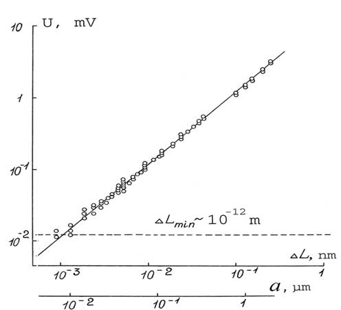
Fig.2. The results of multistage measurements and calibration procedures in subnanometer range of displacements. The minimum value of resolved displacement is DLmin ~ 1 pm.
The random root-mean-square error - r.m.s. deviation from linearity for the transform factor k is less than 0.5-0.6%, while the least value of the resolved interferometer mirror displacement DLmin ~ 1 pm (or 10-12 m) has been achieved. The full dynamic range of our system is near of 210 dB of displacement amplitude when the mentioned above recording steps are accounted.
IV. Precise laser interferometry application
We have applied the precise interferometer servo-system in the fundamental physical measurements and technology tests. The high instrument resolution allows the number of physical parameters to be measured with very high accuracy. They are displacements, strains, optical density variations, the wavelength and velocity of light etc. It was the precise Earth's strain detection that had initiated the developments of high sensitive long-path laser interferometer instruments [4,6].Our contribution to the strain geophysical measurements has provided the small values of the lunar tides of the Earth (low frequencies - up to 10-5 Hz) [11] and microstructure of wide frequency band distributions of geodynamical wave fields [8-12]. We had also participated in an approach to the precise interferometers building for the measurement the effect of the light non-reciprocity in gravitational field [13], and for study of unusual seismic signal propagation [10,14].
As an example of technology application of our precise interferometry technique below we present some results of the piezo-electric transducer (PZT) testing. During a long term of our experiences we investigated a number of transducers which had various quantities of displacement-to-voltage gain (DVG). We have been interested of linearity and reproducibility of their characteristics which are very important to the precise interferometric measurements. We had to take into account the obtained results for accurate calibration procedure of our interferometer servo-system as it was described above. Fig.3 shows two outcomes from a number of measurement cycles of displacement-voltage dependencies for one of the investigated PZT prototypes.
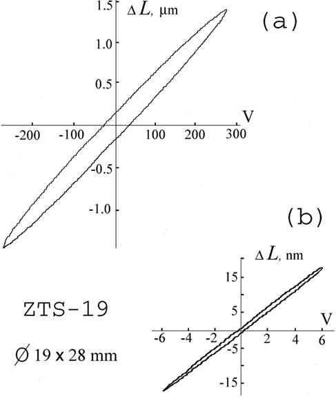
Fig.3. The hysteresis cycles of PZT displacement-voltage dependencies for the ZTS-19 prototype have been measured by the interferometer servo-system in high (a) and low (b) voltage ranges.
We can see here the hysteresis shape of these dependencies while the value of DVG is varied in the 20-50% range when the voltage supplied to the ceramics is too high: 200 V and more (Fig.3a). The mean DVG value is near 5 nm/V in this range. The transducer's reproducibility can achieve 100-200 nm if the hysteresis loop is unlocked. The linearity becomes significantly better for the small voltage variations such as 1-10 V (Fig.3b). The mean DVG value is about 3 nm/V with less than 2-3% hysteresis deviations. Reproducibility is near 1 nm in this range. The visible non-linearity steps in both outcomes (Fig.3a,b) are caused by resolution limit of the X-Y analogue recorder applied in these experiments. We used the PZT prototypes which ensured 0.5-0.6% accuracy of displacements in the effective voltage range to investigate the precision of our interferometer servo-system. The above experimental results (Fig.2) are quite reliable verification of the applied technique.
The interferometer system resolution has been proven by the geophysical application of our instruments. The laser strain gauge has allowed the weak semidiurnal tide wave S2 of amplitude as small as 4 nm to be refined at the 16-meter basis [11]. The interferometer accuracy will increase in subnanometer range of displacements if the instrument length is diminished. In Fig.4 the servo-system outcome (a) and the result of its processing (b) for a short base L = 2 m interferometer are presented.
Fig.4. The dynamic range expander enables the servo-system to operate in ±20 nm recording regime: after removal of the track ruptures (a) the signal amplitude has been accurately measured (b).
The interferometer outcome is recorded by servo-system which is supplied with the dynamic range expander. The device operates permanently in ±20 nm range (recording steps of λ / 32 = 19.8 nm could be observed on Fig 4a, the degree of range expansion m = 16). The full pick-to-pick signal amplitude of 39.5 nm has been measured by the interferometer servo-system. The experimental proving of the developed interferometry technique resolution in 1-35 Hz frequency band has been presented in our previous publication [10]. The value of 1 pm outcome threshold for the interferometer servo-system was demonstrated.
V. Conclusion
The developed precise interferometry technique allows the sub-nanometer displacements to be measured with accuracy of 1% and better. The noise level of the interferometer servo-system is reduced up to 1 pm. Its amplitude dynamic range is estimated to be near of 210 dB. This technique would be useful for high precision measurements in fundamental physical experiments, geophysical observations, and nano-technology tests and control.
Acknowledgements
This work is dedicated to the memory of Prof. R. F. Matveev who guided our investigation over last 30 years. The study is supported by the Russian Foundation of Basic Research, project N02-05-64720.
R e f e r e n c e s
1 J. Lawall and E. Kessler, Michelson interferometry with 10 pm accuracy. Rev. Sci. Instrum., v.71, Iss.7, pp.2669-2676 (2000).
2 H. Boersch, H. J. Eichler, M. Pfundstein, and W. Wiesemann, J. Quant. Electron. v.QE-3, p.501 (1974).
3 A. Araya, K. Kawabe, T. Sato, N. Mio, and K. Tsubono, Highly Sensitive Wide-Band Seismometer Using a Laser Interferometer. Rev. Sci. Instrum., v.64, Iss. 5, pp.1337-1341 (1993).
4 V. Valy, Measuring Earth strains by laser. Sci. Am., v.220, N6, pp.89-100 (1969).
5 M. N. Dubrov, Servo-system for optical interferometers. Avt. Sv. SSSR / Patent RF, N720292, G01B 9/02 (1975 / 1992).
6 V. A. Alyoshin and M. N. Dubrov, Long-path laser interferometers for geophysical measurements. Manuscripta Geodaetica, v.9, N3, pp.231-242 (1984).
7 V. A. Alyoshin, A. S. Gorshkov, M. N. Dubrov, I. P. Ivanov, and A. G. Skepko, Laser interferometer for strain observations in Surkhob tectonic fault region. Izvestiya AN SSSR, Fizika Zemli, N3, pp.80-87 (1986).
8 M. N. Dubrov and V. A. Alyoshin, Laser strainmeters: new developments and earthquake prediction application. Tectonophysics, v.202, N3-4, pp.209-213 (1992)
9 V. A. Alyoshin, M. N. Dubrov, and A. P. Yakovlev, Geophysical laser strainmeter of an adit type. Fizika Zemli, N4, 62-68 (1993).
10 M. N. Dubrov, V. A. Alyoshin, High-precision laser interferometer in multicomponent measuring systems. Journal of Radio Electronics, www journal, http://jre.cplire.ru/jre/oct00/4/text.html, (2000).
11 M. N. Dubrov, V. A. Alyoshin, and A. P. Yakovlev, Wideband laser strainmeters as a new instrument for geophysical research. Gerlands Beitr. Geophysik, v.98, N4, pp.292-300 (1989).
12 M. N. Dubrov, L. A. Latynina, R. F. Matveev, and A. V. Ponomarev, Observations of very long period strain oscillations of the Earth’s surface due to small variations in the atmospheric pressure. Izvestiya, Physics of the Solid Earth, v.34, N12, pp.983-990 (1998).
13 G. N. Izmaylov, F. A. Nikolaev, M. N. Dubrov, V. A. Alyoshin, and V. E. Parakhin, Stable laser interferometer for arrangement of precise physical experiments. Zhurnal Tekhn. Fiz. v.57, N6, pp.1194-1197 (1987).
14 M. N. Dubrov, R. F. Matveev, V. A. Volkov, L. A. Latynina, A. V. Ponomarev, in Proceedings: The Ninth International Symposium on Recent Crustal Movements (CRCM'98, November 14-19, 1998), Cairo - Egypt, Vol. 1, pp. 167-178 (2000).
![]()
Авторы:
Дубров Мстислав
Николаевич, e-mail:
![]()
Алешин Владимир Андреевич
Институт радиотехники и электроники РАН, Фрязинская часть
|
|
оглавление |
|

