| "ÆÓÐÍÀË ÐÀÄÈÎÝËÅÊÒÐÎÍÈÊÈ" N 10, 2000 |
AN ELECTRODYNAMIC ANALYSIS OF A COUPLED DIELECTRIC WAVEGUIDE BAND PASS FILTER
Sergey E. Bankov, Shahadi Meri
Institute of Radio Engineering and Electronics of RAS
Received 18 October 2000
An electrodynamic problem for band pass filter on the base of coupled dielectric waveguides is considered. The original problem is reduced to an integral equation written relatively magnetic current. In its turn the equation is solved by the Galerkins technique. Finally scattering parameters of the filter are obtained and studied. Numerical results are compared with the results obtained in the approach of coupled wave theory.
1. Formulation of the problem
It is well known that dielectric waveguides are promising for millimeter - wave applications. Therefore research and design works directed to development of microwave components on the base of dielectric waveguides are important. Filter or multiplexer is an important part of any communication system such as for example LMDS (Local Multi - Point Distribution System) which operates at frequencies close to millimeter - wave range. A novel filter on the base of co-directionally coupled lines was studied in /1/. Theory of coupled waves /2/ was used for description of these filters. An important advantage of this theory is that it can be formulated independently on the type of transmission line that forms the filter. However this generalization requires some sufficient approximations that are character for the mentioned theory. As a result procedures of filter synthesis and analysis proposed in /1/ should be verified by rigorous solutions of electrodynamic problems. Such a solution for filter on the base of coupled H – dielectric waveguides (HDW) (see fig. 1) is presented in this article.
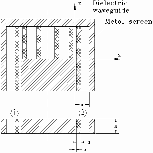
Filter shown in fig.1 has a plane of symmetry (dashed line). All the elements of the filter are supposed to be without dissipative loss. An electrodymanic problem is formulated in the following way. A dominant mode of waveguide at z<0 excites port 1 of the filter. One has to find electromagnetic field in the structure that satisfies to all the boundary conditions and Maxwell’s equations. Also one has to define scattering parameters of the filter.
2. Integral equation
At the first step of the solution we reduce our problem to an integral equation. Before to do it we have to make some important notes. Firstly, mentioned symmetry of the structure allows one to apply method of symmetry in terms of which final result for the filter may be obtained from analysis of two structures shown in fig. 2.
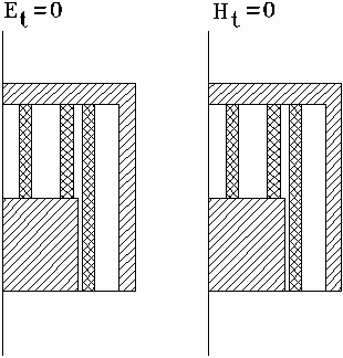
Both structures (fig. 2) are “halves” of the original one. The only difference between them is that in one case an electric wall is placed in the plane of symmetry while in another case a magnetic wall is used. Let us use indexes “e” and “m” to indicate parameters corresponding to partial structures with electric and magnetic walls respectively. The following known formulas connect S-parameters of “halves” with S-parameters of the filter:
where ![]() are S-parameters of the filter and S11, m,e are reflection
coefficients from partial structures with electric and magnetic walls.
are S-parameters of the filter and S11, m,e are reflection
coefficients from partial structures with electric and magnetic walls.
Solutions for partial structures with different walls are absolutely identical. Thus it is reasonable to consider in details only one structure for example with electric wall.
The second important circumstance is connected with a specific character of electromagnetic field in HDW. It is known /4/ that the dominant mode of HDW valids to a two-dimensional Maxwell’s equations. This property of the field takes a place not only in a regular waveguide but also in any regular along OY axis structure like our filter. We mean saying regular along OY axis that parameters of the media between planar screens do not depend on y for arbitrary x and z. Thus one can conclude that all the fields and currents in our filter do not depend on y.
It is possible to propose several ways to obtain integral equation for the filter. We consider only one of them the most simple for numerical solution. Let us divide a structure shown in fig. 3 on two parts II and I. Then let us place at the boundary of these regions perfectly conducting wall. Regions I and II have enough simple shape to obtain in analytical form Green’s functions for them. However presence of the mentioned conducting wall perturbs field and should be compensated in some a way.
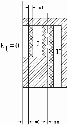
The standard way is to place on the wall’s surfaces magnetic currents. Because of two-dimensional character of the structure field in it has only three components: Ey,Hx,Hz. Therefore magnetic currents on the wall’s surfaces have only one component Imz. Now our task is to satisfy to boundary conditions at x=0, 0<z<L. Tangential components of the electromagnetic field should be continuous at this place. Magnetic currents in region I and II (left and right sides of the wall) are connected with components of electric field:
where indexes + and – correspond to x=+0 and x=-0 respectively.
Thus taking ImzI=-ImzII=Imz
one can satisfy to the boundary condition for electric field. In case of
magnetic field situation is much more complicated because magnetic field is
connected with magnetic current by a Green type function. As it was mentioned
above these functions may be found. We will not describe in details solutions of
the corresponding electrodynamic problems and present only the final results.
Field in the region I is presented as a sum of eigen modes of metal waveguide.
We consider region I as a waveguide which axis is oriented along OX axis. Width
of the waveguide is L. It is shorted at the left end. This waveguide is not
regular. In regions occupied by HDW it is filled with dielectric media with
relative dielectric constant ![]() .
However eigen functions of the waveguide do not depend on properties of media
and may be expressed in form of trigonometric functions
.
However eigen functions of the waveguide do not depend on properties of media
and may be expressed in form of trigonometric functions  ,
n=1,2,… Input admittance at plane x=0 Yn for every eigen mode may
be calculated with help of theory of microwave circuits. Characteristic
admittance and propagation constant of the n-th wave in regions without and with
dielectric (Y1n, Y2n, g 1n, g 2n respectively) may be expressed in the
following way:
k is a free space wavenumber.
Finally an expression for HzI may be written as follows:
Magnetic field in region II is presented as the following integral:
where

![]()
One should take into account that in region II except field excited by magnetic current an additional field produced by an incident wave exists. This field contains incident wave and a wave reflected from perfectly conducting wall at z=L. Boundary conditions for additional field are satisfied everywhere except plane x=0, 0<z<L. Thus total magnetic field in region II may be written as follows:

b 0 is a HDW dominant mode propagation constant.
As it is seen from (7) incident wave has amplitude of magnetic field at x=0 equal to unit.
Magnetic fields HzI and HzII should be equal in interval 0<z<L. Equalizing them we obtain required integral equation:
3. Solution of integral equation
An effective solution of the equation (8) may be obtained by Galerkin technique. One has to take unknown magnetic current as a sum of known functions fn(z) with unknown coefficients An:
Galerkin technique allows one to obtain the following system of linear algebraic equations:
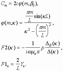
This system may be solved numerically. An important step of practical application of Galerkin technique is a choice of basis functions fn(z) and an order of system. Physical content of the problem allows one to take into account the following factors. Filter is a resonance system. Field near resonance frequency has a dominant component – eigen oscillation. In our case resonator is a simple line shorted at both ends and therefore its eigen function (for Ey component) is

where R is an order of resonance (L=Rl w/2, l w – waveguide wavelength). Thus it is reasonable to take basis functions as follows:
because one of these functions (n=R) is an eigen function of our resonator and therefore one can hope that coefficients An quickly decrease when difference between n and R growths. (System (10), (11) is written under condition (12)). It means that reduced system (10) may be written in the following way:
where Q=0,1,… (2Q+1 is an order of reduced system). Number Q may be determined numerically.
Supposing that An are known one can obtain the following expression for reflection coefficient S11e:
Solution in case of the structure with magnetic wall is absolutely identical to described above one. The only difference is in calculation of input admittances Yn.
4. Computational features
The main problem of the numerical solution is a calculation
of coefficients of system (10). These coefficients are
expressed as integrals from zero to infinity. Sub integral functions
independently on n and m have typical for electrodynamics peculiarities: poles
when parameter of integration ![]() ,
where
,
where ![]() is a propagation constant
of a dominant mode in region II (In general case sub integral function has
several couples of poles. Additional couples correspond to non-dominant
propagated modes. Thus described above case corresponds to waveguide with one
propagated mode). Fortunately convergence of integrals at infinity in our case
is enough fast. Sub integral function decreases at infinity as 1/
is a propagation constant
of a dominant mode in region II (In general case sub integral function has
several couples of poles. Additional couples correspond to non-dominant
propagated modes. Thus described above case corresponds to waveguide with one
propagated mode). Fortunately convergence of integrals at infinity in our case
is enough fast. Sub integral function decreases at infinity as 1/![]() 3.
It is enough for effective numerical calculation of the corresponding integral.
Thus the only problem is an integration of function with poles. Solution of this
problem is well known. Let us write sub integral function in the following way:
3.
It is enough for effective numerical calculation of the corresponding integral.
Thus the only problem is an integration of function with poles. Solution of this
problem is well known. Let us write sub integral function in the following way:
where Res(f(![]() 0))
is a residue of sub integral function at pole
0))
is a residue of sub integral function at pole ![]() ,
,
![]() is an arbitrary constant. One
can see that the first term in (15) is a regular function
without poles. The second term has these poles but it may be integrated
analytically. The final result for integral may be written as follows:
is an arbitrary constant. One
can see that the first term in (15) is a regular function
without poles. The second term has these poles but it may be integrated
analytically. The final result for integral may be written as follows:
5. Numerical results
Numerical solution of system (13) has several goals. The first one is to define an enough for acceptable tolerance number of basis functions. The second goal is to compare rigorous solution with an approximate one obtained in terms of coupled waves theory /2/. Finally the third goal is to investigate some interesting electrodynamic phenomena in the structure.
Numerical calculations show that system (13) rapidly converges to a stable result that does not depend on number Q. Effectivity of numerical solution depends on a relative width of filter pass band. The more narrow it is the less number of basis functions is required. This fact is illustrated in fig. 4 where two plots of S21 modulus versus frequency are shown.
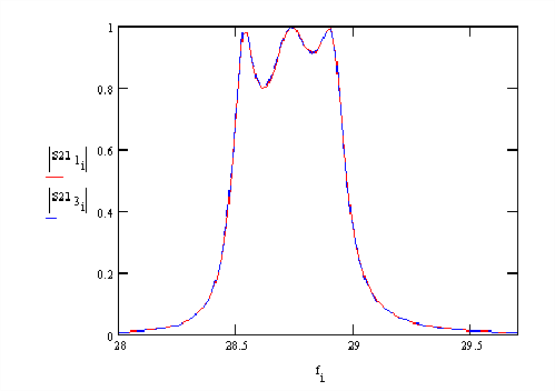
These plots correspond to one filter. The only difference between them is that red curve is calculated with help of one basis function while blue curve with help of three basis functions. One can see that the difference between two curves is negligible. It means that in some practically interesting situations system (13) may be reduced to one equation. Numerical effectivity in this case is extremely high. Additional basis functions are required only for relative pass bands about 15-20% and more.
Theory of coupled waves as it is shown in /1/ allows one to synthesize a band pass filter with required characteristic. However this synthesis gives only an approximate result. For example in fig. 5 two dependencies of filter insertion loss versus frequency are shown. These plots correspond to band pass filter with parameters synthesized in coupled wave theory approach. The solid red curve is obtained with help of electrodynamic solution while dashed blue curve with help of approximate approach.
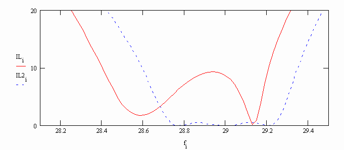
It is easy to see that theory of coupled waves gives a result close to required perfect Chebyshev frequency response of the filter. The result obtained in electrodynamic approach has some differences from a perfect one. Thus approximately synthesized parameters should be corrected to obtain required response of the filter in electrodynamic approach. One should take into account that compared results are obtained for filter with short waveguides. Length of waveguide is equal to half of waveguide wavelength (R=1). Compared solutions have the greatest difference in this situation. It is much smaller when length of waveguide is greater.
Frequency response of the filter with corrected parameters is shown in fig. 6. Now it is really close to Chebyshev response of the third order (dashed curve corresponds to filter with original parameters which response is obtained in coupled wave theory approach).
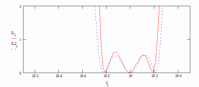
Original and corrected parameters of the filter are presented in table 1. One can see that difference between them is not sufficient. Thus it is possible to conclude that theory of coupled waves may be used as a first approach for synthesis an analysis of filters with coupled dielectric waveguides.
|
Parameters |
Original values |
Corrected values |
|
L |
4.827 |
4.744 |
|
S0 |
0.5 |
0.523 |
|
S1 |
3.015 |
2.965 |
|
S2 |
1 |
1 |
|
S3 |
1.885 |
1.861 |
|
b |
1.2 |
1.2 |
|
d |
1 |
1 |
LITERATURE
1. Банков С.Е., Мери Ш. Cинтез и анализ фильтров на основе линий передачи с сонаправленной распределенной связью // В сб. Антенны, выпуск 1 (42), 1999, с. 67-73.
2. Miller S.E. Coupled Wave Theory and Waveguide Applications – “BSTJ”, 1954, v.33, N3, p. 661-720.
3. A.A. Sayyah and K. Wu Efficient Analysis of Microstrip-Coupled Nonradiative Dielectric Resonators for Hybrid Integrated Circuits // Trans. on MTT, v. 47, N2, 1999, pp. 216-223.
4. Взятышев В.Ф. Диэлектрические волноводы // М.: Сов. Радио, 1970.
Authors:
Bankov Sergey, doctor of science IRE RAS
Shahadi Meri, postgraduate student.