| "ЖУРНАЛ РАДИОЭЛЕКТРОНИКИ" "JOURNAL OF RADIOELECTRONICS" N 8, 1999 |
Vladimir A. Vanke
Faculty of Physics, Moscow State University
Russian experience in the field of non-traditional microwave electronics based on electron beam transverse waves using is discussed in a form of short review.
I. Introduction
The purpose of this report is to inform briefly on some microwave physics research at Moscow State University and Russian Industries*.
In modern microwave systems of radio-location, communication and navigation the strictest requirements are placed on a powerful output amplifier and a low-noise input device. Each of them should satisfy a complex of demands which, unfortunately, are inconsistent. It should be emphasized that linearity of these devices has been realized today to be a decisive parameter.
For the output amplifier the linearity must be combined with a high level of power, a broad range of operational frequencies and a high efficiency.
For the input receiver cascade it is important that the linearity should be combined with stability against overloads, protection of subsequent cascades against these overloads and rapid recovery. At the same time, a low noise figure should be provided in combination with a wide dynamic range and high values of the gain.
Besides, in connection with successful developing ideas of Wireless Power Transmission there appeared a new problem, namely, the problem of back conversion of microwave energy into the energy of direct current. It is not impossible that in future microwave technology would find its wide-scale application in this field.
When applying the conventional longitudinal grouping of electrons in bunches in vacuum microwave electronics (TWTs, Klystrons, etc.) there appear some principle problems connected with the non-linear character of Coulomb forces which usually play a decisive role in forming dense electron bunches.
To a considerable extent, these problems can be bypassed (eliminated), if we apply a transverse grouping of the electron beam drifting in a longitudinal magnetic field.
It was in Russia that this advantageous type of interaction was consistently studied and applied in two past decades.
Now, a few words about the history of the appearance and development of the concept of the transverse grouping in electron beams. The first fundamental and brilliant work was published in 1949 by C.L.Cuccia [1] in the USA. His research was devoted to interaction of the electron beam with the resonator transverse field. Ten years later, nearly simultaneously in the USA and Russia there appeared publications on parametric and, later, electrostatic amplifiers using a fast cyclotron wave of the electron beam. Record values of the amplifier noise temperature, those of the order of 60-200 K, were achieved quite soon [2,3]. In Russia the research in this field was successfully carried on mainly in Moscow State University, Istok Corp. and Tory Corp. [3-6].
Today, the existing three-dimensional models of the electron beam and accumulated experimental experience give us confidence as to possibilities of designing a new class of microwave devices with unique sets of parameters. It is such information that is the main aim of this report.
In the case of transverse modulation of the electron beam drifting in the longitudinal constant magnetic field, four kinds of waves can be excited: two cyclotron waves and two synchronous waves. In each case the beam assumes the shape of a uniformly charged spatial helix having no space charge bunches. It should again be pointed out that it is this circumstance that insures the linearity of the process of energy exchange with external fields.
In contrast to space charge waves, phase velocities of cyclotron waves are dependent on the cyclotron frequency, that is on the value of the constant magnetic field, whose distribution along the interaction region is fixed and determined by the external magnetic system only. Phase velocities of synchronous waves are equal to the longitudinal velocity of the electron beam. All the four transverse waves are circularly polarized.
Stability of phase velocities of transverse waves and their circular polarization provide a high level of selectivity in interaction with circularly polarized fields of electrodynamics structures, which ultimately makes it possible to achieve unique values of parameters in devices based on interaction with transverse waves of the electron beam.
II. Cyclotron
Wave Protector and Parametric AmplifierThe simplest device which interacts selectively with a fast cyclotron wave of the electron beam is a resonator with a transverse electric field. At the cyclotron resonance is capable of transmitting practically all microwave power from the external circuit into the fast cyclotron wave of the electron beam and/or extract the power of this wave back into the external circuit. Two resonators connected in series interact with the electron beam quite efficiently and signal attenuation in such a system can be very low (of the order of 0.5 dB and less).
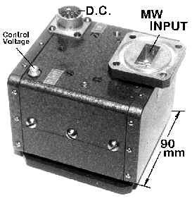
Fig 1. Cyclotron Wave Protectors at 9 and 35 GHz developed by Istok Corp.
At high levels of the input signal the electron beam is trapped by the input resonator bars and the resonators turn out to be disconnected. Thus, there appears a possibility to design a good protective device which could be placed between the antenna and the input amplifier of the receiver (for example, in radars). In the case of the beam trapping in the input resonator the conditions for matching the conductivities of the electron beam and the external circuit are sharply violated. The VSWR is increased up to a few tens of units and the main part of power is reflected from the input of such a device. Thus, high acceptable levels of input power, deep protection and short recovery time are typical of such devices (Fig. 1).
If an additional microwave pump resonator with a quadrupole electric field is placed between the input and output resonators and fed from the external generator with a frequency about the double cyclotron frequency, we shall have a parametric amplifier of the degenerate type which retains all the protective functions of the previous device. Besides, here the input resonator efficiently removes noises of the fast cyclotron wave of the electron beam. At the late 50-s - early 60-s such amplifiers were designed and constructed both in the USA and in Russia.
The idler channel can easily be eliminated by introducing an additional (compensating) electron beam. To amplify cyclotron waves in these beams, quadrupole fields of equal intensity but opposite phases are used.
III.
Cyclotron Wave Electrostatic AmplifierInstead of a microwave pump resonator, it is possible to use an electrostatic quadruple helix forming a spatially twisted electrostatic quadrupole field. The electrons moving along such a system 'feel' the time-variable electric field, and the amplitudes of the electron beam cyclotron waves will be increased if the resonance condition at the double cyclotron frequency is fulfilled. Amplification of a fast cyclotron wave in such a system is achieved due to active coupling with a slow cyclotron wave that does not interact with the input resonator field. A high value of the magnetic field at the cathode surface and subsequent reduction of this value provide a low noise level of cyclotron waves in the electron beam at the entrance into the interaction region.
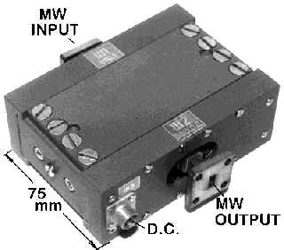
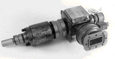
Fig. 2. A Version of Cyclotron Wave Electrostatic Amplifier (Istok Corp.)
In Fig. 2 one can see a general view of a variant of the electrostatic amplifier which is manufactured today by Russian industry only (in total about 10 000 devices have been sold by Istok Corp.) [4,5]. The input amplifier of this type is unique, it provides a low level of intrinsic noises, wide dynamic range, stability to overloads, protection of subsequent receiver cascades and short recovery time after overloads.
A tunable CWESA can be designed if a system with a travelling wave, for example, usual combs are used as couplers. In this case for electron beam potential typical of CWESA, a high degree of selectivity in energy exchange with a fast cyclotron wave of the electron beam is preserved. Operational band of such couplers is narrow (of the order of 1 percent or smaller), however, it can be tuned within a wide range by changing the magnetic field strength and the beam potential.
IV.
Circularly Polarized TWTNow, one should dwell on another interesting possibility of designing Circularly Polarized TWT. Each electron injected along the axis of a circularly polarized slow wave at the velocity equal to the phase velocity of this wave will be equally and monotonously decelerated by the longitudinal field of this wave. The transverse electric field of the wave combined with the longitudinal constant magnetic field (the Lorenz force) will move the electron to the region of the decelerating electric field of the circularly polarized wave. It should be pointed out that this is the case for each electron regardless of the time of its entrance into the wave field. Thus, a filamentary electron beam remains mono-energetic after such an interaction and can be recuperated efficiently.
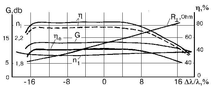
In Fig 3 you can see the results of computer simulation and optimization of such CP TWT. The electron efficiency is about 40%. The efficiency with recuperation up to 80% in the frequency band is of the order of 30%.
Fig. 3. CP TWT characteristics.
G - gain,
It is very important that the non-linearity of the phase-frequency characteristics in non-linear regimes turns out here to be several orders smaller than in ordinary TWT. This is a direct consequence of a new type of spatial grouping of the electron beam, which is not accompanied by formation of electron bunches.
A slow-wave system in the shape of a spatially twisted well-known two-row comb may be used to create different phase velocities of circularly polarized waves with the right and left polarizations.
Double-cascade CP TWT with good values of the parameters is also feasible.
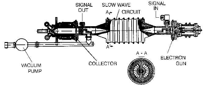
The basic experiment was performed in Russia at the time when no adequate theory was available to describe the electron beam of a finite cross-section and there were no possibilities for optimization of the device. Nevertheless, serviceability of such CP TWT was demonstrated at the CW output power of about 2 kW (Fig. 4). The experimental results obtained at that time were used later to verify the constructed three-dimensional theory and they were found to be in a good agreement.
Fig. 4. A scheme of experimental CP TWT tested by Tory Corp.
The second optimized experiment was designed but its technological realization had to be suspended because of general financial problems.
In our opinion, it is powerful versions of CP TWT that can possess unique parameters and are advantageous for many technological applications.
V. Cyclotron Wave Converter of Microwaves into DC
There appear new tasks in connection with promising tendencies and successful experiments with systems for energy transmission by microwave beams. Therefore it is necessary to design a simple, reliable and powerful device for back conversion of microwave energy into the energy of direct current.
We studied CWC (Cyclotron Wave Converter) both theoretically and by experiment. The energy is introduced into a fast cyclotron wave of the electron beam, converted into the energy of longitudinal motion in the region of the reverse magnetic field and then during recuperation in the collector decelerating field it is released at the outside load of the collector.
Such device is advantageous because it can have a high efficiency at a high power level, stability to overloads in high-frequency and low-frequency circuits, and a high output direct voltage [6].
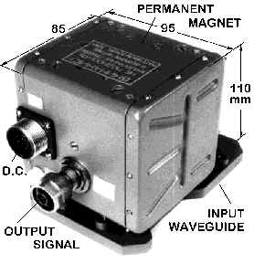
Fig. 5. A version of CWC developed by Tory Corp.
A good experimental device was developed jointly by MSU and Tory Corp (Fig.5). At continuous input power of 10 kW the efficiency was up to 83%.
At Moscow University the CWC was tested for the power level of 30-60 Watt at the efficiency of around 70-74%.
At present, the work is also under way to design CWC at the Istok Corp.
VI.
Klystron with Combined InteractionOne more promising idea should be outlined. It involves combined (longitudinal-transverse) interaction to broaden the operating band of powerful Klystrons.
At the first stage an ordinary Klystrons grouper forms electron bunches. Then they are injected into the region of reverse magnetic field biased with respect to its axis. At the region output a large part of the longitudinal energy of the electron beam can be converted into its rotational energy. Besides, if the cyclotron resonance condition is fulfilled, all the bunches would happen to be on one straight line rotating as a whole around the Z axis. In the resonator with the transverse electric field this energy can be almost completely extracted from the electron beam. The transverse electric field of the resonator gap is uniform and the spreading of bunches in the longitudinal direction is not important, while continuous interaction provides 10-15 times more efficient load of the resonator by the electron beam. Thus, at high efficiency (75-80%) the interaction band of the order of 8-10% and even more can be provided.
VII. Conclusion
In conclusion we should again point out the principal advantages of devices based on interaction with cyclotron and synchronous waves of the electron beam:
*
The absence of non-linearity connected with formation of space charged bunches. Relativistic (non-linear) dependence of the electron mass on the electron energy is not used here.*
Stability of phase velocities and circular polarization of transverse waves make it possible to provide a high level of selectivity in energy exchange with external electromagnetic fields.*
Levels of microwave power in the electron beam can significantly exceed the initial energy of the injected electron beam.These factors, which seem to be quite simple, allow us to overcome a number of limitations which restrict today the development of microwave vacuum electronics.
As a result of application of these new principles of electron beam grouping,
VARIOUS DEVICES with unique parameters for different purposes can be created:*
CYCLOTRON-WAVE PROTECTORS (CWPr) with super high self-protection against high power microwave overloads (up to 500 -1000 kW in pulse), short restoration time (1-5 ns), low voltage supply, small size and weight for use as first element of radar and/or communication receiving systems.*
LOW-NOISE CYCLOTRON WAVE PARAMETRIC AMPLIFIERS (CWPA) and CYCLOTRON WAVE ELECTROSTATIC AMPLIFIERS (CWESA) with low noise temperature (30-100 K), super high self-protection against microwave overloads (up to 500 kW in pulse), short restoration time (1-10 ns), extremely linear phase characteristics, low voltage supply, small size and weight;*
NARROW-BAND CONTROLLED CWESA-FILTERS with low noise temperature (100-200 K), high-speed control of frequency band in wide range (up to 50%), high self-protection and short restoration time (1-10 ns);*
HIGH POWER CIRCULARLY POLARIZED TRAVELLING WAVE TUBES (CPTWT) with high efficiency (about 35-40% into the load and up to 70-80% with recuperation), wide bandwidth (up to 20-30%) and extremely linear phase characteristics;*
HIGH POWER CYCLOTRON-WAVE CONVERTERS (CWC) with efficiency of conversion of microwaves into D.C. up to 80-90%, high output power level - up to 50-100 kW, output voltage range - 10-100 kV;*
KLYSTRONS WITH COMBINED /longitudinal-transverse/ INTERACTION (KCI) with extended bandwidth (up to 8-10%) and high efficiency (75-80%) for various power levels (up to 50 kW);*
CYCLOTRON-WAVE PHASE SHIFTERS (CWPS) for various power levels (from 10 W to 50 kW) with wide phase control range (0 - 360 grad), low signal losses (0.5-1 dB), high-speed phase control.One group of devices is already manufactured commercially, another group is under industrial tests or just passed these tests, the third group is under laboratory tests, and finally, there are a great number of interesting and perspective designs based on reliable experimental data.
An international cooperation will be perspective in this field of microwave electronics.
1. C. L. Cuccia, ‘The Electron Coupler - a Developmental Tube for Amplitude Modulation and Power Control at UHF,’ RCA Rev., 1949, vol.10, p. 270.
2. W. H. Louisell, ‘Coupled Mode and Parametric Electronics,’ John Wiley & Sons, Inc., New York, London, 1960.
3. V. M. Lopukhin, et al, ‘Noises and Parametric Phenomena in Electron Beams,’ Nauka, Moscow, 1966 (in Russian
4. Yu.A. Budzinsky, S. P. Kantyuk, ‘A New Class of Self-Protecting Low-Noise Microwave Amplifiers,’ Proc. IEEE MTT-S Microwave Symposium, Atlanta, USA, June 1993, Digest, vol. 2, p. 1123.
5. V. A. Vanke, H. Matsumoto, N. Shinohara, ‘A New Microwave Input Amplifier with High Self-Protection and Rapid Recovery,’ IEICE Trans. on Electronics (Japan), 1998, vol. E81-C, p. 788
* Updated version of the article (in .pdf format)
Author: Vanke Vladimir Alexandrovich, e-mail: vanke@mesps.phys.msu.su