SCATTERING OF DIPOLE FIELD BY PERFECTLY CONDUCTING
DISK
Vadim A. Kaloshin 1, Kirill K. Klionovski 2
1 Kotelnikov Institute of Radioengineering and Electronics of RAS
2 JSC «Concern «Morinformsystem-Agat»»
The paper is received on December 2, 2013
Abstract. Asymptotic formulas for calculating a scattering field of an arbitrarily oriented magnetic and electric dipole located on axis of a perfectly conducting disk were obtained using the method of physical theory of diffraction and the method of uniform asymptotic theory of diffraction. Radiation patterns were calculated using the asymptotic formulas and a numerical solution of a singular integral equation. The obtained results were compared to ones available in literature. A dependence of the front-to-back ratio on the disk’s radius was investigated.
Keywords: perfectly conducting disk, spherical wave, dipole, physical theory of diffraction, uniform asymptotic theory of diffraction.
Introduction.
Scattering of electromagnetic waves by a perfectly conducting disk was researched in [1-33]. In particular, scattering of a plane electromagnetic wave by a perfectly conducting disk was considered in [1-15]. Scattering of field of an electric and magnetic dipole located on axis of a disk was researched in [16-32]. A paper [33] describes a scattering field of an electric dipole located arbitrarily relative to a disk. A special case of a dipole mounted on a surface of a disk was presented in [16-25]. Asymptotic expressions of a scattering field of an electric dipole with perpendicular to disc orientation are available in [19, 25, 29]. Asymptotic formulas of a scattering field of a magnetic dipole with parallel orientation are available in [20]. A rigorous solution is available in a case of a perpendicular electric [16, 17] and parallel magnetic [17] dipole. This solution is represented as a series of spheroidal functions.
The statement of problem.
The first purpose of present paper is obtaining asymptotic expressions for a scattering pattern of an electric and magnetic arbitrarily oriented dipole located on an axis of a perfectly conducting disk. The second purpose of the paper is obtaining a numerical solution of this problem. The third one is to compare numerical results obtained using the asymptotic expressions and the numerical solution with numerical results from the papers [19, 20, 29].
We considered two cases - the dipole oriented parallel and normally to the disk (Fig. 1). It is enough to determine the field of the arbitrarily oriented dipole.
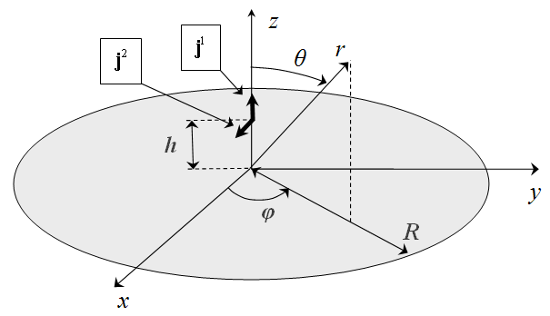
Fig. 1. The dipoles on axis of the perfectly conducting disk
The asymptotic expressions for scattering pattern derived separately near and far from the axis Z. We use the uniform asymptotic theory of diffraction [34, 35] to determine the scattering field far from the axis, and results of paper [36] near the axis. The results of paper [36] were obtained in the physical theory of diffraction approximation [3].
Fields of the dipoles in free space.
Consider a perpendicular magnetic dipole
and a parallel magnetic dipole
in free space where, x, y, z are Cartesian coordinates; z0 and x0 are the unit vectors in direction of the Z-axis and the X-axis, respectively; δ(x) – is the Dirac delta function; mz, mx – are moments of the magnetic dipoles.
Azimuthal and meridional components of field of the magnetic dipoles in free space are

in a case of the perpendicular magnetic dipole, and

in a case of the parallel magnetic dipole. Here, λ is wavelength; r, θ, φ are spherical coordinates. Bottom indexes θ and φ correspond to the meridional and azimuthal field component, respectively.
Consider a perpendicular electric dipole
and a parallel electric dipole
Here, pz, px – are moments of the electric dipoles. Components of field of the perpendicular and parallel electric dipole in free space are respectively

and

The asymptotic expressions of field far from the axis.
Let’s define the
asymptotic expressions for meridional ![]() and azimuthal
and azimuthal ![]() components of field of the electric
and magnetic dipoles. The dipoles locate on the axis of the disk of radius R
on distance h above the disk (Fig. 1). These expressions for the angles far
from the Z-axis in the uniform asymptotic theory of diffraction approximation
are
components of field of the electric
and magnetic dipoles. The dipoles locate on the axis of the disk of radius R
on distance h above the disk (Fig. 1). These expressions for the angles far
from the Z-axis in the uniform asymptotic theory of diffraction approximation
are


The meridional
![]() and azimuthal
and azimuthal ![]() component in (9), (10)
corresponds to the meridional and azimuthal component in (3), (4), (7) or (8) of
analyzed dipole
component in (9), (10)
corresponds to the meridional and azimuthal component in (3), (4), (7) or (8) of
analyzed dipole ![]() ,
, ![]() ,
, ![]() or
or ![]() , respectively. The
variable
, respectively. The
variable ![]() for a perpendicular magnetic dipole or a parallel
electric dipole. The variable
for a perpendicular magnetic dipole or a parallel
electric dipole. The variable ![]() for a parallel magnetic dipole or a perpendicular
electric dipole. The variable
for a parallel magnetic dipole or a perpendicular
electric dipole. The variable ![]() for perpendicular magnetic and electric
dipoles, and
for perpendicular magnetic and electric
dipoles, and ![]() for parallel magnetic and electric dipoles.
In (9), (10)
for parallel magnetic and electric dipoles.
In (9), (10)  is the Heaviside function. Function
  is first term of
asymptotic representation of the Fresnel integral
is first term of
asymptotic representation of the Fresnel integral  . The arguments of the functions
 ![]() and
and ![]() are
are

Formulas (9) and (10) take into account the first and the second order of diffraction. The last term in (9) describes the second order of diffraction and it is determined using the uniform geometrical theory of diffraction.
The asymptotic expressions of field near the axis.
Let’s define asymptotic expressions near from the Z-axis. These expressions in the physical theory of diffraction approximation have the form

for the meridional component of field, and

for the azimuthal component of field. The scattering field in (12), (13) is determined as

for the perpendicular magnetic dipole,

for the parallel magnetic dipole,

for the perpendicular electric dipole, and

for the parallel electric dipole.
The meridional
component ![]() and the azimuthal component
and the azimuthal component ![]() in (12)-(17) correspond
to the meridional and azimuthal component in (3), (4), (7) or (8) of analyzed dipole
in (12)-(17) correspond
to the meridional and azimuthal component in (3), (4), (7) or (8) of analyzed dipole
![]() ,
, ![]() ,
, ![]() or
or ![]() , respectively. In
(14)-(17) Jn(u) is the Bessel function of order n and
argument u, and
, respectively. In
(14)-(17) Jn(u) is the Bessel function of order n and
argument u, and

Let’s define the
front-to-back ratio ![]() for the parallel electric and magnetic dipoles. We define
asymptotic expressions of the front-to-back ratio in the physical theory of
diffraction using the asymptotic expressions (12), (15) and (17) near the Z-axis:
for the parallel electric and magnetic dipoles. We define
asymptotic expressions of the front-to-back ratio in the physical theory of
diffraction using the asymptotic expressions (12), (15) and (17) near the Z-axis:

for the parallel magnetic dipole, and

for the parallel electric dipole, where

The expressions (19), (20) take the next form when the radius of the disk tends to infinity

for the parallel magnetic dipole, and
for the parallel electric
dipole. Expression (21) shows that the front-to-back ratio of the magnetic
dipole oscillate relative a constant when the radius of the disk increase. This
constant and amplitude of oscillation doesn’t depend on the disk’s radius. This
dependence of ![]() can be explained by the fact that an amplitude
of field of the magnetic dipole on an edge of the disk decreases proportionally
R. At the same time, amplitude of scattering field by the edge increases proportionally
R. As a result, the front-to-back ratio oscillates relative to a
constant value.
can be explained by the fact that an amplitude
of field of the magnetic dipole on an edge of the disk decreases proportionally
R. At the same time, amplitude of scattering field by the edge increases proportionally
R. As a result, the front-to-back ratio oscillates relative to a
constant value.
Expression (22) shows that ![]() of the electric dipole is
infinite when
of the electric dipole is
infinite when ![]() . In this case, amplitude of field of the dipole on
the edge of the disk decreases proportionally
. In this case, amplitude of field of the dipole on
the edge of the disk decreases proportionally ![]() , and
, and ![]() increases in proportion to the disk’s radius.
increases in proportion to the disk’s radius.
Numerical research of scattering by a disk.
The scattering by a disc was investigated by solving a singular integral equation of the first kind
numerically. Here, ![]() is the Green’s tensor;
is the Green’s tensor; ![]() is the unknown electric
current on the disk;
is the unknown electric
current on the disk; ![]() is electric field of a dipole in
free space;
is electric field of a dipole in
free space; ![]() is surface of the disk. We used the
method of moments and an algorithm described in [37] to solve the integral
equation (23). The unknown electric current
is surface of the disk. We used the
method of moments and an algorithm described in [37] to solve the integral
equation (23). The unknown electric current ![]() shall be decomposed over basis of triangular elements:
shall be decomposed over basis of triangular elements:

Here, ![]() are unknown current’s amplitudes; r0
is the radial unit vector; φ0 is the azimuthal unit
vector. Basic functions with bases 2Tr and
2Tφ have the form
are unknown current’s amplitudes; r0
is the radial unit vector; φ0 is the azimuthal unit
vector. Basic functions with bases 2Tr and
2Tφ have the form

for perpendicular magnetic dipole, and

parallel electric and magnetic dipoles were considered. The method of moments reduces the problem of scattering to a system of linear algebraic equations. A matrix of the unknown current’s amplitudes can be determined solving this system:
Elements of matrix of own and mutual
impedances ![]() are calculated by numerical
integration of the Green's tensor components
are calculated by numerical
integration of the Green's tensor components ![]() and the basic functions:
and the basic functions:

A representation of components ![]() in spectral form was used during calculations of the
own and "nearest" mutual impedances in the matrix
in spectral form was used during calculations of the
own and "nearest" mutual impedances in the matrix ![]() . The basic function was decomposed into a
two-dimensional Fourier integral over flat sheets of electric current. Integral
over the surface S´ in (28) was determined by integrating fields
of the flat sheets with components
. The basic function was decomposed into a
two-dimensional Fourier integral over flat sheets of electric current. Integral
over the surface S´ in (28) was determined by integrating fields
of the flat sheets with components ![]() . A representation
. A representation ![]() in source-wise form for a ring of radial and
azimuthal current in the spherical coordinates was used for purpose of reducing
computation time in calculating the "distant" mutual impedances in the
matrix
in source-wise form for a ring of radial and
azimuthal current in the spherical coordinates was used for purpose of reducing
computation time in calculating the "distant" mutual impedances in the
matrix ![]() . Elements of a matrix
. Elements of a matrix ![]() which describes an interaction of field of a dipole
and the current of the disk have the following form:
which describes an interaction of field of a dipole
and the current of the disk have the following form:

The scattering field is determined by summing the field of dipole (3), (4), (7) or (8), and the field of the electric current of the disk. The field of the disk’s electrical current is determined by numerical integration of fields of radial and azimuthal electrical current’s rings. The integration was performed over radius of the rings with amplitude distribution (24).
The numerical results.
A pattern of the perpendicular magnetic dipole located on distance h=0,4λ above the disk of radius R=2λ and R=0.5λ is shown in Fig. 2 and 3, respectively. Red curve plots were obtained using numerical solution of the integral equation. Blue curve plots were obtained using asymptotic equations of the field near the Z-axis (13), (14). Green curve plots were obtained using asymptotic equation of the field far from the Z-axis (10).
Figures 4-7
show patterns of the parallel magnetic dipole which mounts on the surface of
the disk of radius R=2λ and R=0.5λ. Curves in Fig. 4, 6 show patterns in Е-plane  . Curves
in Fig. 5, 7 show patterns in Н-plane
. Curves
in Fig. 5, 7 show patterns in Н-plane ![]() . Red curve plots were obtained using
numerical solution of the integral equation. Blue curve plots were obtained using
asymptotic equations of the field near the Z-axis (12), (15) in Fig. 4,
6, and (13), (15) in Fig. 5, 7. Green curve plots were obtained using
asymptotic equation of the field far from the Z-axis (9) in Fig. 4, 6,
and (10) in Fig. 5, 7. Violet and cyan curves plot were obtained using
asymptotic equations [20] of the field far and near from the Z-axis,
respectively.
. Red curve plots were obtained using
numerical solution of the integral equation. Blue curve plots were obtained using
asymptotic equations of the field near the Z-axis (12), (15) in Fig. 4,
6, and (13), (15) in Fig. 5, 7. Green curve plots were obtained using
asymptotic equation of the field far from the Z-axis (9) in Fig. 4, 6,
and (10) in Fig. 5, 7. Violet and cyan curves plot were obtained using
asymptotic equations [20] of the field far and near from the Z-axis,
respectively.
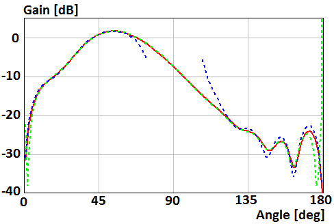
Fig. 2. Gain of the perpendicular magnetic dipole above the disk of radius R=2λ
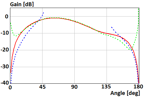
Fig. 3. Gain of the perpendicular magnetic dipole above the disk of radius R=0.5λ
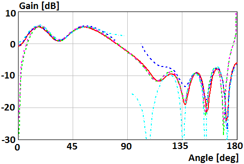
Fig. 4. Gain of the parallel magnetic dipole which mounts on the surface of the disk of radius R=2λ in Е-plane
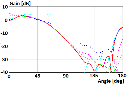
Fig. 5. Gain of the parallel magnetic dipole which mounts on the surface of the disk of radius R=2λ in Н-plane
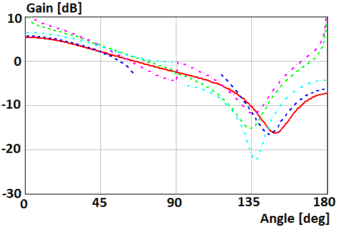
Fig. 6. Gain of the parallel magnetic dipole which mounts on the surface of the disk of radius R=0.5λ in Е-plane
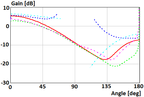
Fig. 7. Gain of the parallel magnetic dipole which mounts on the surface of the disk of radius R=0.5λ in Н-plane
Patterns for a case of the perpendicular electric dipole which mounts on the surface of the disk of radius R=2λ and R=0.5λ are shown in Fig. 8 and 9, respectively. Blue curve plots were obtained using asymptotic equations of the field near the Z-axis (12), (16). Green curve plots were obtained using asymptotic equation of the field far from the Z-axis (9). Violet and cyan curves plot were obtained using asymptotic equations [19] of the field far and near from the Z-axis, respectively.
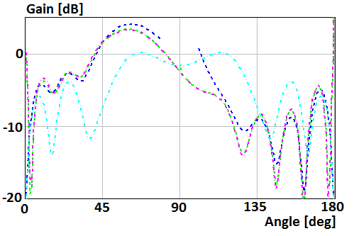
Fig. 8. Gain of the perpendicular electric dipole which mounts on the surface of the disk of radius R=2λ
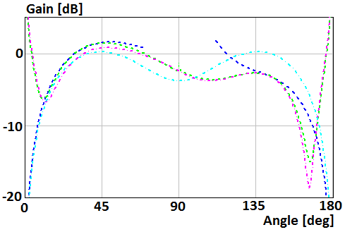
Fig. 9. Gain of the perpendicular electric dipole which mounts on the surface of the disk of radius R=0.5λ
Figures 10-13
show patterns for the case of the parallel electric dipole located on distance
h=0,4λ above the disk of
radius R=2λ and R=0.5λ. Curves in Fig. 10, 12 show patterns in Е-plane ![]() . Curves
in Fig. 11, 13 show patterns in Н-plane
. Curves
in Fig. 11, 13 show patterns in Н-plane ![]() . Red curve plots were obtained using
numerical solution of the integral equation. Blue curve plots were obtained using
asymptotic equations of the field near the Z-axis (12), (17) in Fig. 10,
12, and (13), (17) in Fig. 11, 13. Green curve plots were obtained using
asymptotic equation of the field far from the Z-axis (9) in Fig. 10, 12,
and (10) in Fig. 11, 13.
. Red curve plots were obtained using
numerical solution of the integral equation. Blue curve plots were obtained using
asymptotic equations of the field near the Z-axis (12), (17) in Fig. 10,
12, and (13), (17) in Fig. 11, 13. Green curve plots were obtained using
asymptotic equation of the field far from the Z-axis (9) in Fig. 10, 12,
and (10) in Fig. 11, 13.
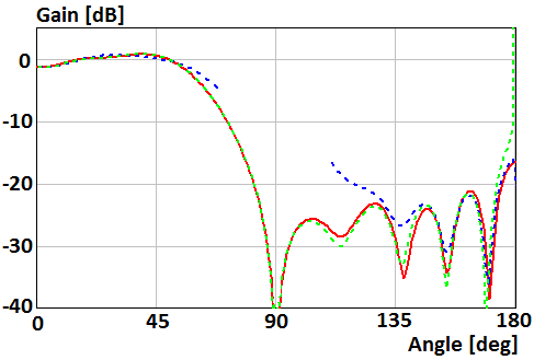
Fig. 10. Gain of the parallel electric dipole above the disk of radius R=2λ in Е-plane
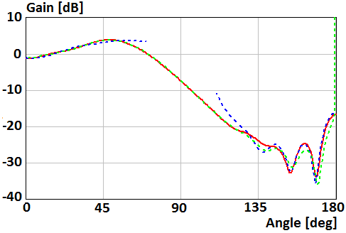
Fig. 11. Gain of the parallel electric dipole above the disk of radius R=2λ in Н-plane
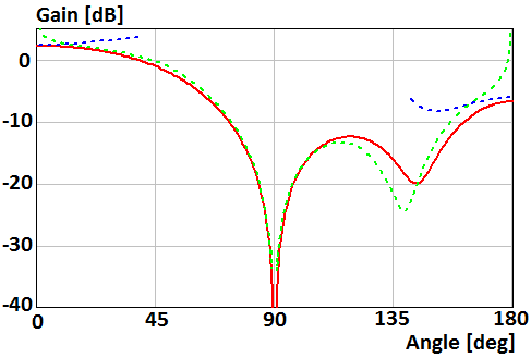
Fig. 12. Gain of the parallel electric dipole above the disk of radius R=0.5λ in Е-plane
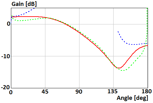
Fig. 13. Gain of the parallel electric dipole above the disk of radius R=0.5λ in Н-plane
Plots 14, 15 show dependence of the front-to-back ration of the parallel magnetic and electric dipoles on radius of the disk. The magnetic and electric dipoles locate on distances h=0,5λ and h=0,75λ above the disk, respectively. The disk’s radius is presented in proportions of wavelength. Red curves in Fig. 14 and 15 were obtained using asymptotic equations (19) and (20), respectively. Blue curve in Fig. 14 plots was obtained using asymptotic equation (21). Green points in Fig. 14 and 15 t were obtained using numerical solution of the integral equation.
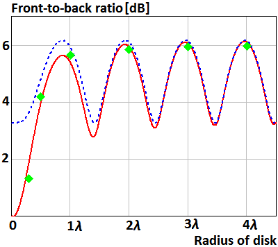
Fig. 14. The front-to-back ratio of the parallel magnetic dipole above the disk
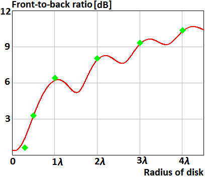
Fig. 15. The front-to-back ratio of the parallel electric dipole above the disk
Let’s discuss
the calculation results in a case when radius of the disk is 2λ. The asymptotic expressions of field
near the axis describe radiation pattern with relative accuracy less than 1 dB
for sector of angles ![]() and
and ![]() . The asymptotic expressions of field far from the
axis describe radiation pattern with relative accuracy less than 1 dB for
sector of angles
. The asymptotic expressions of field far from the
axis describe radiation pattern with relative accuracy less than 1 dB for
sector of angles ![]() , except the case of the parallel magnetic dipole in H-plane
for angles
, except the case of the parallel magnetic dipole in H-plane
for angles ![]() . Curves of radiation pattern obtained using the
asymptotic expressions near and far from the axis coincide for sectors of
angles
. Curves of radiation pattern obtained using the
asymptotic expressions near and far from the axis coincide for sectors of
angles ![]() and
and ![]() . Sector of coinciding increases when the disk radius increases.
The relative accuracy of obtained asymptotic expressions decreases to 4 dB for angles
. Sector of coinciding increases when the disk radius increases.
The relative accuracy of obtained asymptotic expressions decreases to 4 dB for angles
![]() in a case of the
disk’s radius is 0.5λ.
in a case of the
disk’s radius is 0.5λ.
The relative accuracy of obtained asymptotic expressions of field near the axis is better than relative accuracy of the asymptotic expressions [20]. Analysis shows that asymptotic formulas obtained in [29] for radiation pattern of perpendicular electric dipole located on the disk are incorrect.
The asymptotic expressions of the front-to-back ratio of the parallel electric and magnetic dipoles allow determining this ratio with accuracy less than 0.3 dB for any radius of the disk.
Conclusions.
Asymptotic expressions for calculating a scattering field of an arbitrarily oriented magnetic and electric dipole located on axis of a perfectly conducting disk were obtained. The asymptotic formulas make possible to calculate scattering field in full space. A relative accuracy of the asymptotic formulas is less than 1 dB when radius of the disk more then 2λ. The asymptotic expressions for the front-to-back ratio have the accuracy less than 0.3 dB for any radius of the disk.
REFERENCES
1. Лурье К. А. Дифракция плоской электромагнитной волны на идеально проводящем тонком диске // ЖТФ. 1959. № 12. С. 1421–1433.
2. Hansen E. B. Scalar diffraction by an infinite strip and a circular disc // Journ. of Math. and Physics. V. 41. № 3. 1962. pp. 229–245.
3. Уфимцев П. Я. Метод краевых волн в физической теории дифракции. М.: Сов. радио. 1962.
4. Хёнл Х., Мауэ А., Вестпфаль К. Теория дифракции. М.: Мир. 1964.
5. Diane P. Marsland, Constantine A. Balanis, Stephen A. Brumley Higher order diffractions from a circular disk // IEEE Trans. on Anten. and Prop. V. AP-35. № 12. Dec. 1987. pp. 1436–1444.
6. Akashi T., Ando M., Kinoshita T. Effect of multiple diffraction in PTD analysis of scattered field from a conducting disk // Trans. IEICE. V. E-72. № 4. 1989. pp. 259–261.
7. Ando M., Kinoshita T. Accuracy comparison of PTD and PO for plane wave diffraction from large circular disk // Trans. IEICE. V. E-72. № 11. 1989. pp. 1212–1218.
8. Ando M., Kinoshita T. PO and PTD analysis in polarization prediction for plane wave diffraction from large circular disk // Digests of 1989 IEEE AP/S Int. Symp. V. 3. 1989. pp. 1282–1285.
9. Allen K. Dominek Transient scattering analysis for a circular disk // IEEE Trans. on Anten. and Prop. V. AP-39. № 6. June 1991. pp. 815–819.
10. Li L. W., Kooi P. S., Qiu Y. L., Yeo T. S., and Leong M. S. Analysis of electromagnetic scattering of conducting circular disk using a hybrid method // PIER. V. 20. 1998. pp. 101–123.
11. Zalipaev V., Kostin A. Scattering of a plane electromagnetic wave by a perfectly conducting disk in the high-frequency approximation // in proc. of int. seminar «Day on Diffraction 2001». 2001. pp. 311–319.
12. Hongo K. and Naqvi Q. A. Diffraction of electromagnetic wave by disk and circular hole in a perfectly conducting plane // PIER. V. 68. 2007. pp. 113–150.
13. Balaban M. V., Sauleau R., Benson T. M., and Nosich A. I. Dual integral expressions technique in electromagnetic wave scattering by a thin disk // PIER. V. 16. 2009. pp. 107–126.
14. Сухаревский И. О., Залевский Г. С., Нечитайло С. В., Сухаревский О.И. Рассеяние электромагнитной волны круглым идеально проводящим диском конечной толщины // Электромагнитные волны и электронные системы. 2010. № 2. С. 42–47.
15. Hongo K., Jafri A. D. U., and Naqvi Q. A. Scattering of electromagnetic plane wave by a circular disk with surface impedance // PIER. V. 127. 2012. pp. 501–522.
16. Leitner A., Spence R. D. Effect of a Circular Ground Plane on Antenna Radiation // Journ. of Appl. Physics. Oct. 1950. V. 21. №10.
17. Белкина М. Г. Дифракция электромагнитных волн на диске // В сб.: Дифракция электромагнитных волн на некоторых телах вращения. М.: Сов. радио. 1957. С. 148–174.
18. Lopez A. R. The geometrical theory of diffraction applied to antenna pattern and impedance calculation // IEEE Trans. on Anten. and Prop. V. AP-14. № 1. Jan. 1966. pp. 40–45.
19. Пименов Ю. В. Излучение элементарного электрического вибратора, расположенного в центре идеально проводящего круглого диска // Антенны. 1968. вып. 3. С. 93–102.
20. Пименов Ю. В., Брауде Л. Г. Излучение элементарного щелевого вибратора, расположенного в центре идеально проводящего диска // Антенны. 1969. вып. 6. С. 89–105.
21. Hahn K.F., Fikioris J.G. Impedance and Radiation Pattern of Antennas above Flat Discs // IEEE Trans. on Anten. and Prop. Jan. 1973. V. AP-21. № 1. pp. 97–100.
22. Awadalla K. H., Maclean T. S. M. Monopole antenna at center of circular ground plane: input impedance and radiation pattern // IEEE Trans. on Anten. and Prop. V. AP-27. № 2. Mar. 1979. pp. 151–153.
23. Jack H. Richmond Monopole antenna on circular disk // IEEE Trans. on Anten. and Prop. V. AP-32. № 12. Dec. 1984. pp. 1282–1287.
24. McNamara D. A., Pistorius C. W. I., Malherbe J. A. G. Introduction to the uniform geometrical theory of diffraction. Norwood, MA.: Artech house. 1990.
25. Volakis J. L. Antenna Engineering Handbook Fourth Edition. McGraw Hill Professional. 2007.
26. Гринберг Г. А., Пименов Ю. В. К вопросу о дифракции электромагнитных волн на бесконечно тонких идеально проводящих плоских экранах // ЖТФ. 1957. №10. С. 2326–2339.
27. Inawashiro S. Diffraction of electromagnetic waves from an electric dipole by a conducting circular disk // Journal of Physics Society. Japan. V. 18. 1963. pp. 273–287.
28. Пименов Ю. В., Давыдов А. Г. О влиянии идеально проводящей плоскости с круглым отверстием на излучение элементарного магнитного вибратора // Радиотехника. 1978. т. 33. № 7. С. 91–94.
29. Пименов Ю. В., Давыдов А. Г. Излучение вертикального электрического вибратора, расположенного на оси идеально проводящего диска // Изв. ВУЗов. Радиофизика. 1980. т. 23. № 1. С. 101–112.
30. Duan D. W., Rahmat-Samii Y. and Mahon J. P. Scattering from a circular disk: Comparative study of PTD and GTD techniques // Proc. of IEEE. V. 79. № 10. 1991. pp. 1472–1480.
31. Murasaki T., Sato M., Ando M., Goto N. Diffraction Analysis of a Flat Plate for Dipole Wave Incidence Using the Modified Edge Representation // Proc. of ISAP. 1992. pp. 569–572.
32. Кравченко В. Ф., Ерофеенко В. Т. Дифракция электромагнитных волн, излучаемых магнитным диполем, на сверхпроводящем тонком диске // Радиотехника. 1995. №10. С. 65–70.
33. Hongo K., Jafri A. D. U., and Naqvi Q. A. Scattering of electromagnetic spherical wave by a perfectly conducting disk // PIER. V. 129. 2012. pp. 315–343.
34. Боровиков В. А., Эйдус А. Г. О сравнении двух методов вычисления поля в области полутени // Антенны. Вып. 29. 1981. С. 49–55.
35. Kouyoumjian R. G., Pathak P. H. A uniform geometrical theory of diffraction for an edge in a perfectly conducting surface // Proc. IEEE. V. 62. № 11. 1974. pp. 1448–1461.
36. Калошин В. А., Попов А. П. Рассеяние на осесимметричной кромке // РЭ. 1984. № 8. С. 1502–1509.
37. Клионовски К. К. Характеристики направленности проводящих экранов круглой формы // Антенны. 2011. № 12. С. 31–37.