|
|
"JOURNAL OF RADIO ELECTRONICS" N 2, 2001 |
|
SMART
ANTENNA APPLICATION FOR SATELLITE COMMUNICATION SYSTEMSĀ WITH SPACE DIVISION MULTIPLE ACCESS
V. Zaharov, F. Casco, M. Gutierrez
Departamento de Ingenieria Electrica, Universidad AutonomaĀ Metropolitana - Iztapalapa,
Mexico D.F., MEXICO
Received February 05, 2001
Ā
Two different beamforming approaches in space division multiple access (SDMA) for mobile satellite communications: switched-beam antennas and adaptive array antenna systemsĀ are considered. The algorithm that meets both the Ālow computational complexity and high convergence requirements in the adaptive array antenna system of SDMA are developed. The hardware implementation of adaptive algorithm is considered as well.
1. INTRODUCTION
In the satellite communication systems , as a rule, many users are active in the same time. Since resources of the systems (the transmitting power, the bandwidth) are limited, it is advisable to use the channels with complete charge i.g. to create the multiple access to channel. This generates a problem of summation and separation of signals in the transmission and reception parts respectively. Deciding of this problem consists in the development of orthogonal channels of transmission in order to divide signals from various users unambiguously on reception part.Ā Currently the methods of multiple access widely use so as time division multiple access (TDMA), frequency division multiple access (FDMA) and code division multiple access (CDMA), as well as their combination [1,2,3].
The significant factor in the performance of multiple access in a satellite communications system is interference. It causes cross-talk, missed or dropped calls, and upsets customers. Most importantly, interference limits traffic-carrying capacity from the finite RF spectrum. Interference can come from another users, other cell sites operating on the same frequency, or out-of-band RF energy leaking into the allocated spectrum. The most usual types of interference are co-channel interference and adjacent channel interference. Co-channel interference is caused by transmissions from non-adjacent cells using the same set of frequencies, where there is minimal physical separation from neighboring cells using the same frequencies. Adjacent channel interference is caused by RF leakage on the subscriber's channel from a neighboring cell using an adjacent frequency. This can occur when the user's signal is much weaker than that of the adjacent channel user.Ā Signal to interference ratio (SIR) is an important indicator of call quality; it is a measure of the ratio between the mobile phone signal (the carrier signal) and an interfering signal. A higher SIR ratio means increasing overall system capacity.
Taking into account, what in the systems of satellite communications every user has own unique space position, this fact maybe used for the separation of channels in the space and as consequence to increase SIR ratio. Such method is named Space Division Multiple Access (SDMA) [3]. More perspective from the point of view the realizations of systems SDMA is applying of smart antenna array with different level of intelligence consisting from the antenna array and digital processor. Since, the frequency of transmission for satellite communications systems enough high (mostly 6 or 14 GHz), the dimensions of array placed onĀ orbit commensurable with dimensions parabolic antenna, what is necessary condition to put of such systems in orbit. Applying of systems SDMA the most perspective for satellite communications systems for low (till 1500 km) and middle orbits
(till 10000 km), when the signals of users achieve the satellite antenna under different angles (▒22 degrees for the middle orbits). In this instance, ground level maybe split into the zones of service determined by beam pattern lobes in different directions, as shown on figure1.
There are two different beamforming approaches in SDMA for satellite communications: one (Switched-Beam Antennas) is to track each subscriber of a given cell with an individual beam pattern as the target subscriber moves within the cell, and the other (Adaptive Array Antenna Systems) is to select one beam pattern for each subscriber out of a number of preset fixed beam patterns depending on the location of the subscriber.
The work purpose is the description of the SDMA principles in satellite communication systems and development of effective adaptive algorithm with low cost implementation for digital processor.
2. SWITCHED-BEAM ANTENNA
It is possible, using array antennas, to create a group of overlapping beams that together result in omnidirectional coverage. It is the simplest technique, and comprises only a basic switching function between separate directive antennas or predefined beams of an array. Beam-switching algorithms and RF signal-processing software are incorporated in smart antenna designs. For each call, software algorithms determine the beams that maintain the highest quality signal and the system continuously updates beam selection, ensuring that customers get optimal quality for the duration of their call.Ā One might design overlapping beam patterns pointing in slightly different directions similar to the ones shown in figure 1.
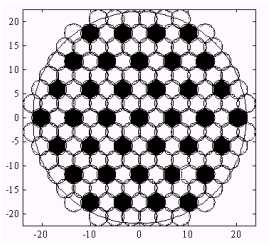
Fig.1Ā The beam patterns for the cover of the earth surface
Every so often, the system scans the outputs of each beam and selects the beam with the largest output power. The black cells in figure1 reuse the frequencies currently assigned to the mobile, so they are potential sources of interference. The use of a narrow beam reduces the number of interfering sources 'seen' at the base station. As the mobile moves, the smart antenna system continuously monitors the signal quality to determine when a particular beam should be selected.
ForĀ switched-beam antenna we shall consider two-dimensional antenna array with Nxelementsin plane x and Nyelements in plane y with distance betweenelements dx and dy accordingly. The expression for the multibeam antenna array we present in the form [4]
 ĀĀĀĀĀĀĀĀĀĀĀĀĀ(1)
where ![]() ,Ā
,Ā ![]() ;
; ![]() Āand
Āand ![]() Āaccordingly angle of elevationĀ and the azimuth of arriving signal which are limited by values Ā
Āaccordingly angle of elevationĀ and the azimuth of arriving signal which are limited by values Ā![]() ;
; ![]() ,
, ![]() Āare some constants determining phase
shifts in planes x and y,
Āare some constants determining phase
shifts in planes x and y, ![]() are the patterns of linear adaptive arrays in
corresponding planes.
are the patterns of linear adaptive arrays in
corresponding planes.
The necessary condition of the signals which coming from various directions to be orthogonal is
Ā![]() . In this case
. In this case ![]() ,
, ![]() ,
, ![]() ,
, ![]() ;Ā
;Ā ![]() ,
, ![]() Āand we obtain
orthogonal spread pattern with
Āand we obtain
orthogonal spread pattern with ![]() ĀĀbeams in the plane x Ķ
ĀĀbeams in the plane x Ķ ![]() Ābeams in the plane Āy Āin which maximum each of beam coincides with zeroes
other. Hereinafter without
loss of generality accept
Ābeams in the plane Āy Āin which maximum each of beam coincides with zeroes
other. Hereinafter without
loss of generality accept ![]() . The resulting pattern of multibeam antenna array we present
in the formĀĀĀĀĀ ĀĀĀĀĀĀĀĀĀĀĀĀĀĀĀĀĀĀĀĀĀ
. The resulting pattern of multibeam antenna array we present
in the formĀĀĀĀĀ ĀĀĀĀĀĀĀĀĀĀĀĀĀĀĀĀĀĀĀĀĀ
 ,ĀĀĀĀĀĀĀ (2)
where for the middle orbitsĀ ![]()
ThusĀ the satellite communication
system SDMA which using switched-beam antennaĀ
present in the form of the orthogonal beamforming scheme.Ā When the signal ui(t) from i-th users with direction of ![]() and
and ![]() Āis arrived of antenna
array input,Ā the output signal of the
beamforming we present as
Āis arrived of antenna
array input,Ā the output signal of the
beamforming we present as
ĀĀĀĀĀĀĀĀ
ĀĀĀĀĀĀĀĀĀĀĀĀĀĀĀĀĀĀĀĀĀĀĀĀĀĀĀĀĀĀĀĀĀĀĀ  .ĀĀĀĀĀĀĀĀĀĀĀĀĀĀĀĀĀĀĀĀĀĀĀ
(3)
.ĀĀĀĀĀĀĀĀĀĀĀĀĀĀĀĀĀĀĀĀĀĀĀ
(3)
In the case when L users are active in the same time the eq.(3) we rewriteĀ in the matrix form
ĀĀĀĀĀĀĀĀĀĀĀĀĀĀĀĀĀĀĀĀĀĀĀĀĀĀĀĀĀĀĀĀĀĀĀĀĀĀĀĀĀĀĀĀĀĀĀĀĀĀĀĀĀĀĀĀĀĀĀĀĀĀĀĀĀĀ ![]() ,ĀĀĀĀĀĀĀĀĀĀĀĀĀĀĀĀĀĀĀĀĀĀĀĀĀĀĀĀĀĀĀĀĀĀ ĀĀĀĀĀĀĀĀĀĀĀĀĀĀĀĀĀĀĀĀĀĀĀĀĀĀĀ(4)
,ĀĀĀĀĀĀĀĀĀĀĀĀĀĀĀĀĀĀĀĀĀĀĀĀĀĀĀĀĀĀĀĀĀĀ ĀĀĀĀĀĀĀĀĀĀĀĀĀĀĀĀĀĀĀĀĀĀĀĀĀĀĀ(4)
where  Āis resulting
multibeam pattern,
Āis resulting
multibeam pattern,
![]() ,
, ![]()
 ,Ā
,Ā ![]() ,
, ![]() ,
, ![]() Āis an output signal
of beamforming, Xi is N dimensional column vector, ę is transpose
symbol.
Āis an output signal
of beamforming, Xi is N dimensional column vector, ę is transpose
symbol.
The high quality signal (HQS) for the switching beam technique can be determined as follows
ĀĀĀĀĀĀĀĀĀĀĀĀĀĀĀĀĀĀĀĀĀĀĀĀĀĀĀĀĀĀĀĀĀĀĀĀĀĀĀĀĀĀĀĀĀĀ ![]() ĀĀĀĀĀĀĀĀĀĀĀĀĀĀĀĀĀĀĀĀĀĀĀĀĀĀĀĀĀĀĀĀĀĀ(5)
ĀĀĀĀĀĀĀĀĀĀĀĀĀĀĀĀĀĀĀĀĀĀĀĀĀĀĀĀĀĀĀĀĀĀ(5)
Switched-beam antennas are normally used only for reception of signals since there can be ambiguity in the systemÆs perception of the location of the received signal. Switched-beam antennas gives the best performance, usually in terms of received power, but also suppress interference arriving from directions away from the active beamÆs center, because of the higher directivity compared to a conventional antenna, some gain is achieved. In high-interference areas, switched-beam antennas are further limited since their pattern is fixedĀ and they lack the ability to adaptively reject interference. Such an antenna will be easier to implement in existing cell structures than the more sophisticated adaptive arrays, but it gives a limited improvement.
3. ADAPTIVE ARRAY ANTENNA SYSTEMS
Adaptive array antenna systems continually monitor their coverage areas, attempting to adapt to their changing radio environment, which consists of (often mobile) users and interferers. In the simplest scenario - that of a single user and no interferers - the system adapts to the userÆs motion
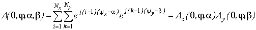
by providing an effective antenna pattern that follows the user, always providing maximum gain in the userÆs direction. The principle of SDMA with adaptive antenna application is quite different from the beam-forming approaches described above (figure 2)Ā
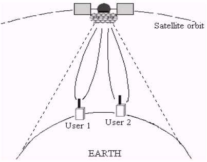
Fig.2Ā The principle of SDMA with adaptive antenna application
The processing of events occurs in SDMA adaptive array antenna systems could be presented as aĀ following sequence:
Ę "Snapshot", or sample, is taken of the signals coming from all of the antenna elements, converted into digital form, and stored in memory.
Ę The SDMA digital processor analyzes the sample to estimate of the radio environment, identifying users and interferers and their locations.
Ę The processor calculates the combining strategy for the antenna signals that optimally recovers the users signals.Ā With this strategy, each userÆs signal is received with as much gain as possible and with the other usersÆ and interferersÆ signals rejected as much as possible.
Ę An analogous calculation is done to allow spatially selective transmission from the array. Each userÆs signal is now effectively delivered through a separate spatial communications channel.
Ę The system now has the ability to both transmit and receive information on each of the spatial channels making them two-way channels.
As result, the SDMA adaptive array antenna system can create a number of two-way spatial channels on a single conventional channel, be it frequency, time, or code. Each of these spatial channels enjoys the full gain and interference rejection capabilities of the array. In theory, an array with m elements can support m spatial channels per conventional channel. In practice, the number is somewhat less because take place the received multipath signals which can be combined to direct received signals. In addition, by using special algorithms and space diversity techniques, the radiation pattern can be adapted to receive multipath signals which can be combined. These techniques will maximize the signal to interference ratio (SIR) (or signal to interference and noise ratio (SINR)).
The more detailed benefits of an SDMA system include the following:
- The number of cells required to cover a given area can be substantially reduced.
- Interference from other systems and from users in other cells is significantly reduced.
- The destructive effects of multipath signals ¢ copies of the desired signal that have arrived at the antenna after bouncing from objects between the signal source and the antenna Ś can often be mitigated.
- Channel reuse patterns of the systems can be significantly tighter because the average interference resulting from co-channel signals in other cells is markedly reduced .
- Separate spatial channels can be created in each cell on the same conventional channel. In other words, intra-cell reuse of conventional channels is possible.
- SDMA station radiates much less total power than a conventional station. One result is a reduction in network-wide RF pollution. Another is a reduction in power amplifier size.
- The direction of each spatial channel is known and can be used to accurately establish the position of the signal source.
- SDMA is compatible with almost any modulation method, bandwidth, or frequency band includingĀ GSM, PHP, DECT, IS-54, IS-95, and other formats. SDMA can be implemented with a broad range of array geometry and antenna types.
Without loosing of generality we will consider only one dimension array but obtained results can be easy spread on two dimension caseĀ using technique presented in [5]. The main parts of smart antenna base station with interchannel signal processing are show in figure3.ĀĀĀĀĀĀ
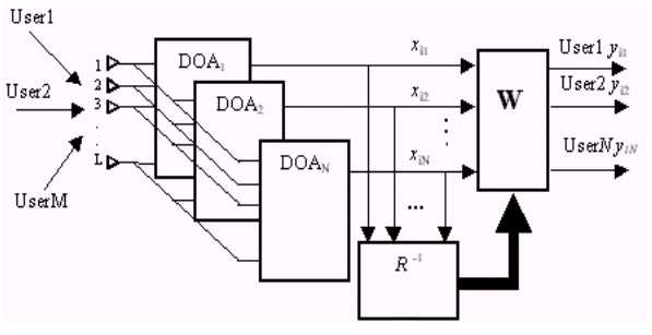
ĀĀĀĀĀĀĀĀĀĀĀĀĀĀĀĀĀĀĀĀĀĀ Fig 3. ĀBlock diagram ofĀ interchannel Āprocessing in smart antennaĀ base station
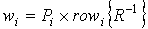
ĀIt consistsĀ L elements array,Ā Direction of Arrival (DOA) matrixes, tracking unit (R-1) and weighting matrix (W).Ā We present the matrix of DOA as N row of the steering vectors
ĀĀĀĀĀĀĀĀĀĀĀĀĀĀĀĀĀĀĀĀĀĀĀĀĀĀĀĀĀĀĀ ĀĀĀĀĀĀĀĀĀĀĀĀĀĀĀĀĀĀĀĀĀĀĀĀĀĀĀĀĀ![]() ,ĀĀĀĀĀĀĀĀĀĀĀĀĀĀĀĀĀĀĀĀĀĀĀĀĀĀĀĀĀĀĀĀĀĀĀĀĀĀĀ (6)
,ĀĀĀĀĀĀĀĀĀĀĀĀĀĀĀĀĀĀĀĀĀĀĀĀĀĀĀĀĀĀĀĀĀĀĀĀĀĀĀ (6)
where ![]() ,
, ![]() ,
, ![]() is i-th reference angle.
is i-th reference angle.
![]() are element space and wave length respectively, T is symbol of transpose.
are element space and wave length respectively, T is symbol of transpose.
When in input of array are affectedĀ signals from M users then the signal at the input of L antenna elementsĀ is given by
ĀĀĀĀĀĀĀĀĀĀĀĀĀĀĀĀĀĀĀĀĀĀĀĀĀĀĀĀĀĀĀĀĀĀĀĀĀĀĀĀĀĀĀĀĀĀĀĀĀĀĀĀĀĀĀĀĀĀĀĀĀĀĀĀĀĀĀĀĀĀĀĀĀĀĀĀĀĀĀĀĀĀĀĀĀĀĀĀĀ
ĀĀĀĀĀ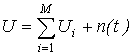 ,ĀĀĀĀĀĀĀĀĀĀĀĀĀĀĀĀĀĀĀĀĀĀĀĀĀĀĀĀĀĀĀĀĀĀĀĀĀĀĀĀĀĀĀĀĀĀĀĀĀĀĀ (7)
where ![]() is signal from i-thĀ
user which satisfy the "narrowband assumption",
is signal from i-thĀ
user which satisfy the "narrowband assumption", ![]() Ā,
Ā, ![]() Āis angle of i-th user
arrival signal, n(t) is zero-mean
thermal noise present in the receiver, PiĀ is the power of the i-th user signal.
Āis angle of i-th user
arrival signal, n(t) is zero-mean
thermal noise present in the receiver, PiĀ is the power of the i-th user signal.
The output signal after DOAÆs matrixĀ when ![]() Āis
Āis
ĀĀĀĀĀĀĀĀĀĀĀĀĀĀĀĀĀĀĀĀĀĀĀĀĀĀĀĀĀĀĀĀĀĀĀĀĀĀĀĀĀĀĀĀĀĀĀĀĀ ![]() ,ĀĀĀĀĀĀĀĀĀĀĀĀĀĀĀĀĀĀĀĀĀĀĀĀĀĀĀĀĀĀĀĀĀĀĀĀĀĀĀĀĀĀĀĀĀĀĀĀĀĀ (8)
,ĀĀĀĀĀĀĀĀĀĀĀĀĀĀĀĀĀĀĀĀĀĀĀĀĀĀĀĀĀĀĀĀĀĀĀĀĀĀĀĀĀĀĀĀĀĀĀĀĀĀ (8)
whereĀ ![]() ,Ā
,Ā ![]() ,Ā
,Ā ![]() ,
,
~Ā is conjugate and transpose symbol.
We will consider the effectiveness of the adaptive system using criteria of signal interference ration maximization (MSIR) by suppressing the signal from interference sources. In case of SIR maximization is to be used, the optimum weight vector W Āis given by
ĀĀĀĀĀĀĀĀĀĀĀĀĀĀĀĀĀĀĀĀĀĀĀĀĀĀĀĀĀĀĀĀĀĀĀĀĀĀĀĀĀĀĀĀĀĀĀĀĀĀĀĀĀĀĀĀĀĀĀĀĀĀĀĀ ![]() ,ĀĀĀĀĀĀĀĀĀĀĀĀĀĀĀĀĀĀĀĀĀĀĀĀĀĀĀĀĀĀĀĀĀĀĀĀĀĀĀĀĀĀĀĀĀĀĀĀĀĀĀĀĀĀĀĀĀĀĀĀĀĀ (9)
,ĀĀĀĀĀĀĀĀĀĀĀĀĀĀĀĀĀĀĀĀĀĀĀĀĀĀĀĀĀĀĀĀĀĀĀĀĀĀĀĀĀĀĀĀĀĀĀĀĀĀĀĀĀĀĀĀĀĀĀĀĀĀ (9)
where ![]() Āis N´N correlation matrix of the total received
signal,
Āis N´N correlation matrix of the total received
signal, ![]() .
.
From eq.(9) follows that weigh vector of i-th user ![]() which maximize SIR relationĀ
in i-thĀ channel of adaptive version in comparison
with no adaptive
which maximize SIR relationĀ
in i-thĀ channel of adaptive version in comparison
with no adaptive
ĀĀĀĀĀĀĀĀĀĀĀĀĀĀĀĀĀĀĀĀĀĀĀĀĀĀĀĀĀĀĀĀĀĀĀĀĀĀĀĀĀĀĀĀĀĀĀĀĀĀĀĀĀ 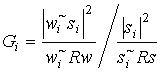 ĀĀĀĀĀĀĀĀĀĀĀĀĀĀĀĀĀĀĀĀĀĀĀĀĀĀĀĀĀĀĀĀĀĀĀĀĀĀĀĀĀĀĀĀĀĀĀĀĀĀĀĀĀĀ(10)
can be obtained as
ĀĀĀĀĀĀĀĀĀĀĀĀĀĀĀĀĀĀĀĀĀĀĀĀĀĀĀĀĀĀĀĀĀĀĀĀĀĀĀĀĀĀĀĀĀĀĀĀ
 .ĀĀĀĀĀĀĀĀĀĀĀĀĀĀĀĀĀĀĀĀĀĀĀĀĀĀĀĀĀĀĀĀĀĀĀĀĀĀĀĀĀĀĀĀĀĀĀĀĀĀĀ (11)
From (11) follows that
ĀĀĀĀĀĀĀĀĀĀĀĀĀĀĀĀĀĀĀĀĀĀĀĀĀĀĀĀĀĀĀĀĀĀĀĀĀĀĀĀĀĀĀĀĀĀĀĀĀĀĀĀĀĀĀĀĀĀĀĀĀĀĀĀĀ ![]() Ā,ĀĀĀĀĀĀĀĀĀĀĀĀĀĀĀĀĀĀĀĀĀĀĀĀĀĀĀĀĀĀĀĀĀĀĀĀĀĀĀĀĀĀĀĀĀĀĀĀĀĀĀĀĀĀĀĀĀĀĀ (12)
Ā,ĀĀĀĀĀĀĀĀĀĀĀĀĀĀĀĀĀĀĀĀĀĀĀĀĀĀĀĀĀĀĀĀĀĀĀĀĀĀĀĀĀĀĀĀĀĀĀĀĀĀĀĀĀĀĀĀĀĀĀ (12)
where P only scale factor for each channel and can be omitted .
The output vector from N channels
ĀĀĀĀĀĀĀĀĀĀĀĀĀĀĀĀĀĀĀĀĀĀĀĀĀĀĀĀĀĀĀĀĀĀĀĀĀĀĀĀĀĀĀĀĀĀĀĀĀĀĀĀĀĀĀĀĀĀĀĀĀĀ ![]() ,ĀĀĀĀĀĀĀĀĀĀĀĀĀĀĀĀĀĀĀĀĀĀĀĀĀĀĀĀĀĀĀĀĀĀĀĀĀĀĀĀĀĀĀĀĀĀĀĀĀĀĀ (13)
,ĀĀĀĀĀĀĀĀĀĀĀĀĀĀĀĀĀĀĀĀĀĀĀĀĀĀĀĀĀĀĀĀĀĀĀĀĀĀĀĀĀĀĀĀĀĀĀĀĀĀĀ (13)
where ![]() ,Ā andĀ x is
input vector after DOA matrix
,Ā andĀ x is
input vector after DOA matrix
ĀĀĀĀĀĀĀĀĀĀĀĀĀĀĀĀĀĀĀĀĀĀĀĀĀĀĀĀĀĀĀĀĀĀĀĀĀĀĀĀĀĀĀĀĀĀĀĀĀĀĀĀĀĀĀĀĀĀĀĀĀĀĀĀ ![]() ĀĀĀĀĀĀĀĀĀĀĀĀĀĀĀĀĀĀĀĀĀĀĀĀĀĀĀĀĀĀĀĀĀĀĀĀĀĀĀĀĀĀĀĀĀĀĀĀĀĀĀĀĀĀ(14)
ĀĀĀĀĀĀĀĀĀĀĀĀĀĀĀĀĀĀĀĀĀĀĀĀĀĀĀĀĀĀĀĀĀĀĀĀĀĀĀĀĀĀĀĀĀĀĀĀĀĀĀĀĀĀ(14)
The output signal atĀ the i-th user channel is given by
ĀĀĀĀĀĀĀĀĀĀĀĀĀĀĀĀĀĀĀĀĀĀĀĀĀĀĀĀĀĀĀĀĀĀĀĀĀĀĀĀĀĀĀĀĀĀĀĀĀĀĀĀĀĀĀĀĀĀĀĀĀĀĀĀĀĀĀĀ
![]() .ĀĀĀĀĀĀĀĀĀĀĀĀĀĀĀĀĀĀĀĀĀĀĀĀĀĀĀĀĀĀĀĀĀĀĀĀĀĀĀĀĀĀĀĀĀĀĀĀĀĀĀĀĀĀĀĀĀĀĀ (15)
.ĀĀĀĀĀĀĀĀĀĀĀĀĀĀĀĀĀĀĀĀĀĀĀĀĀĀĀĀĀĀĀĀĀĀĀĀĀĀĀĀĀĀĀĀĀĀĀĀĀĀĀĀĀĀĀĀĀĀĀ (15)
4. TRACKING ADAPTIVE MODEL
When one use k sample sizeĀ for estimation of weight vector then formula (12) can be rewritten as
Ā
ĀĀĀĀĀĀĀĀĀĀĀĀĀĀĀĀĀĀĀĀĀĀĀĀĀĀĀĀĀĀĀĀĀĀĀĀĀĀĀĀĀĀĀĀĀĀĀĀĀĀĀĀĀĀĀĀĀĀĀĀĀĀĀĀĀĀĀĀĀĀĀ
![]() ĀĀĀĀĀĀĀĀĀĀĀĀĀĀĀĀĀĀĀĀĀĀĀĀĀĀĀĀĀĀĀĀĀĀĀĀĀĀĀĀĀĀĀĀĀĀĀĀĀĀĀĀĀĀĀĀĀ(16)
ĀĀĀĀĀĀĀĀĀĀĀĀĀĀĀĀĀĀĀĀĀĀĀĀĀĀĀĀĀĀĀĀĀĀĀĀĀĀĀĀĀĀĀĀĀĀĀĀĀĀĀĀĀĀĀĀĀ(16)
where 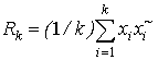 Āis maximum likelihood
estimation of matrix R.
Āis maximum likelihood
estimation of matrix R.
In many of real scenario the input data are nonstationary. We can present this data as a sliding windows with k vectors, each for N elements and denote these data as a matrix X
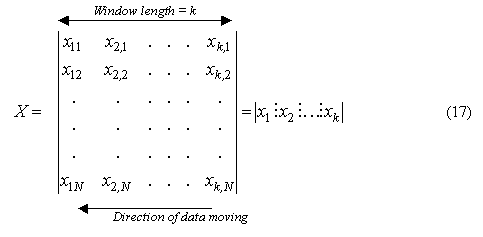
ĀĀĀ
whereĀĀĀĀĀĀ ![]() , i = 1,2,...,k is column vector of i-th sample
("snapshot").
, i = 1,2,...,k is column vector of i-th sample
("snapshot").
Presentation of data as shown in eq.(17) permits apply recursive adaptive algorithm for weight vector modification.Ā Consider RLS algorithm given by one rank matrix modification formula. For this purpose the matrix RkĀ in (16) weĀ write as follows
ĀĀĀĀĀĀĀĀĀĀĀĀĀĀĀĀĀĀĀĀĀĀĀĀĀĀĀĀĀĀĀĀĀĀĀĀĀĀĀĀĀĀĀĀĀ ĀĀĀĀĀĀĀĀĀĀĀ![]() ĀĀĀĀĀĀĀĀĀĀĀĀĀĀĀĀĀĀĀĀĀĀĀĀĀĀĀĀĀĀĀĀĀĀĀĀĀĀĀĀ(18)
ĀĀĀĀĀĀĀĀĀĀĀĀĀĀĀĀĀĀĀĀĀĀĀĀĀĀĀĀĀĀĀĀĀĀĀĀĀĀĀĀ(18)
where
 Āis forgetting
factor,Ā
Āis forgetting
factor,Ā  ,
,
We can rewrite (18) as
ĀĀĀĀĀĀĀĀĀĀĀĀĀĀĀĀĀĀĀĀĀĀĀĀĀĀĀĀĀĀĀĀĀĀĀĀĀĀĀĀĀĀĀĀĀĀĀĀĀ 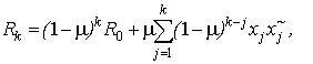 ĀĀĀĀĀĀĀĀĀĀĀĀĀĀĀĀĀĀĀĀĀĀĀĀĀĀĀ(19)
IntroducingĀ of matrix ofĀ coefficients C
ĀĀĀĀĀĀĀĀĀĀĀĀĀĀĀĀĀĀĀĀĀĀĀĀĀĀĀĀĀĀĀĀĀĀĀĀĀĀĀĀĀĀĀĀ ![]() ĀĀĀĀĀĀĀĀĀĀĀĀĀĀĀĀĀĀĀĀĀĀĀĀĀ(20)
ĀĀĀĀĀĀĀĀĀĀĀĀĀĀĀĀĀĀĀĀĀĀĀĀĀ(20)
we can rewriteĀ theĀ matrix X as a weighted matrix by matrix C
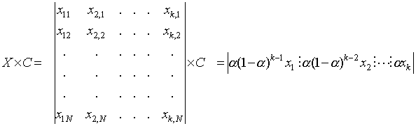 .ĀĀĀĀ (21)
It is well known [6],[7] that ![]() Āis computed without
matrix division using the matrix inversion lemma.ĀĀĀĀĀĀĀĀĀĀĀĀĀĀĀĀĀĀĀĀĀĀĀĀĀĀĀĀĀĀĀĀĀĀĀĀĀĀ
Āis computed without
matrix division using the matrix inversion lemma.ĀĀĀĀĀĀĀĀĀĀĀĀĀĀĀĀĀĀĀĀĀĀĀĀĀĀĀĀĀĀĀĀĀĀĀĀĀĀ
ĀĀĀĀĀĀĀĀĀĀĀĀĀĀĀĀĀĀĀĀĀĀĀĀĀĀĀĀĀĀĀĀĀĀĀĀĀĀĀĀĀĀĀĀ 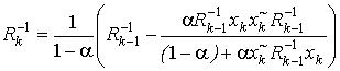 ĀĀĀĀĀĀĀĀĀĀĀĀĀĀĀĀĀĀĀĀĀĀĀĀĀĀ(22)
Even with the powerful signal processor available today it is a very challenging task to performĀ eq.(22) in real time because the computational complexity of this operation O(N2). The base operation of this algorithm is matrix for vector multiplication, that sufficiently large for real time processing.
5. PROPOSED ALGORITHM
Evidently that adaptive algorithm must be implemented with number of Ācontradictory demands. This is, first of all, high convergence to optimum solution, since in low convergence will be seen the high level of interference at the beginning part of connection with subscriber. In the second place, the adaptive algorithm preferably must to have low hardware implementation, since adaptive processorĀ have to put in satellite. The first demand dictates applying of the direct matrix inverse algorithms of adaptation, and second recursive implementation of such algorithms.
The convergence of recursive direct matrix inverse algorithms of adaptation in detail is investigated in [4], [6].
We present recursive least square (RLS) vector operations efficient algorithms for real time weights optimizing and signal tracking that apply eq.(22) with computational complexityĀ O(N). ĀĀApplying of this algorithm for tracking allows decrease its complexity of hardware implementation.
ĀĀĀĀĀĀĀĀĀĀĀĀĀĀĀĀĀĀĀĀĀĀĀĀ
For i = 1,2,...,k the output vector can be obtain as following
ĀĀĀĀĀĀĀĀĀĀĀĀĀĀĀĀĀĀĀĀĀĀĀĀĀĀĀĀĀĀĀĀ 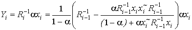 ĀĀĀĀĀĀĀĀĀĀĀĀĀĀĀĀ(23)
where ![]() ,Ā i = 1,2,...,kĀ is output of channels in i-th moment of time .
,Ā i = 1,2,...,kĀ is output of channels in i-th moment of time .
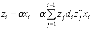
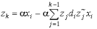
Making substitutionĀĀĀĀĀĀĀĀĀĀĀĀĀĀĀĀĀĀĀĀĀĀĀĀĀĀĀĀĀĀĀĀĀĀĀ
ĀĀĀĀĀĀĀĀĀĀĀĀĀĀĀĀĀĀĀĀĀĀĀĀĀĀĀĀĀĀĀĀĀĀĀĀĀĀĀĀĀĀĀĀĀĀĀĀĀĀĀĀĀĀĀĀĀĀĀĀĀĀĀĀĀĀĀĀĀĀĀĀĀĀĀĀ
![]() ĀĀĀĀĀĀĀĀĀĀĀĀĀĀĀĀĀĀĀĀĀĀĀĀĀĀĀĀĀĀĀĀĀĀĀĀĀĀĀĀĀĀĀĀĀĀĀ(24)
ĀĀĀĀĀĀĀĀĀĀĀĀĀĀĀĀĀĀĀĀĀĀĀĀĀĀĀĀĀĀĀĀĀĀĀĀĀĀĀĀĀĀĀĀĀĀĀ(24)
eq.(23) can be rewriteĀ as
ĀĀĀĀĀĀĀĀĀĀĀĀĀĀĀĀĀĀĀĀĀĀĀĀĀĀĀĀĀĀĀĀĀĀĀĀĀĀĀĀĀĀĀĀĀĀĀĀĀĀĀ 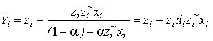 ĀĀĀĀĀĀĀĀĀĀĀĀĀĀĀĀĀĀ(25)
where 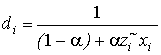 Āis scalar.
Inverse of matrix ![]() then we present as
then we present as
ĀĀĀĀĀĀĀĀĀĀĀĀĀ ĀĀĀĀĀĀĀĀĀĀĀĀĀĀĀĀĀĀĀĀĀĀĀĀĀĀĀĀĀĀĀĀĀĀĀĀĀĀĀĀĀĀĀĀĀĀĀ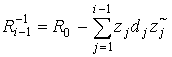 ĀĀĀĀĀĀĀĀĀĀĀĀĀĀĀĀĀĀĀĀĀĀĀĀĀĀĀĀĀĀĀĀĀĀĀĀĀĀĀĀĀĀĀ(26)
Then taking into account eq.(26) we rewriteĀ eq.(24)
ĀĀĀĀĀĀĀĀĀĀĀĀĀĀĀĀĀĀĀĀĀĀĀĀĀĀĀĀĀĀĀĀĀĀĀĀĀĀĀĀĀĀĀĀĀĀĀĀĀĀĀĀĀĀĀĀĀĀĀĀ 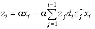 ĀĀĀĀĀĀĀĀĀĀĀĀĀĀĀĀĀĀĀĀĀĀĀĀĀĀĀĀĀĀĀĀĀĀĀĀĀĀĀĀ(27)
Ā
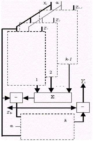
6. SOFTWARE IMPLEMENTATION
The algorithm of output signal obtaining Yi in the i-th moment of time we present in the next stage
1. Initialization
ĀĀĀĀĀĀĀ ![]() ,ĀĀĀ
,ĀĀĀ ![]() .
.
2.ĀĀĀ for i = 1,2,...,k-1ĀĀĀĀĀĀĀĀĀĀĀĀĀ (i is currently sample number )
 ;Ā (training part)ĀĀ
Ā![]() ĀĀĀĀĀĀĀĀĀĀĀĀĀĀĀĀ (processing part)
ĀĀĀĀĀĀĀĀĀĀĀĀĀĀĀĀ (processing part)
end.
3.ĀĀĀ forĀ i = k ,k+1, k+2,...
 ;Ā (training part)
![]() ĀĀĀĀĀĀĀĀĀĀĀĀĀ (processing part)
ĀĀĀĀĀĀĀĀĀĀĀĀĀ (processing part)
ĀĀĀĀĀĀĀĀĀ for j = 2,...,k
ĀĀĀĀĀĀĀĀĀ ![]() ĀĀĀĀĀĀĀĀĀĀĀ(shift in memory that memorize vectors z )
ĀĀĀĀĀĀĀĀĀĀĀ(shift in memory that memorize vectors z )
ĀĀĀĀĀĀĀĀĀ end
In the stage 1 is being put constant ![]() Āand nulling the memory
that stores the vectors z.
Āand nulling the memory
that stores the vectors z.
Then in stage 2 is being filled outĀ the memoryĀ
by no zero elements. The stage 3 is processingĀ of the data in real time. At that, the new vector ![]() Āobtained after
processing part have to shift in the place of
Āobtained after
processing part have to shift in the place of ![]() , the vector
, the vector![]() in the place of
in the place of ![]() and so on.
and so on.
7. HARDWARE IMPLEMENTATION OF THE PROCESSOR
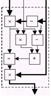
The architecture of processor has shown en figure 4. As follows from this figure the processor consistĀ k identical blocks that presented in figure 5 (k-1 blocksĀ for training procedure and 1 block for sample processing).Ā As follows from figures 4 and 5 it needs approximately 2Nk multipliers and adders to hardware implementation of processor.
8. SIMULATION RESULTS
The sample scenario was created. The antenna array
consists L=20 linearly arranged elements with ![]() spacing. Number of channels N=8. Number of users M=8.
Each sources was simulated as Gaussian distributed with SNR and azimuth
location that have shown in table 1. Algorithm was applied with forgetting
factor
spacing. Number of channels N=8. Number of users M=8.
Each sources was simulated as Gaussian distributed with SNR and azimuth
location that have shown in table 1. Algorithm was applied with forgetting
factor ![]() . Convergence of algorithm was evaluated as number of samples
when parameter Gi no worse
then 3 db in comparison with optimum solution.Ā
200 independent simulations have been averaged.
. Convergence of algorithm was evaluated as number of samples
when parameter Gi no worse
then 3 db in comparison with optimum solution.Ā
200 independent simulations have been averaged.
Table 1.
|
#source |
Angle (degrees) |
SNR(dB) |
Convergence (number of samples) |
|
|
Proposed algorithm |
Conventional algorithm |
|||
|
1 |
-20 |
10 |
46 |
42 |
|
2 |
-15 |
12 |
43 |
42 |
|
3 |
-10 |
15 |
40 |
39 |
|
4 |
-5 |
11 |
41 |
40 |
|
5 |
0 |
17 |
35 |
33 |
|
6 |
5 |
20 |
33 |
28 |
|
7 |
10 |
18 |
38 |
34 |
|
8 |
15 |
15 |
41 |
37 |
The table shown that convergence of proposed algorithm is no worse then 5 samples in comparison with conventionalĀ algorithm, but how follows from part above proposed algorithm have advantage en computational complexity and hardware implementation.
9. SUMMERY
Two approaches for SDMA satellite communication systems are presented: switch beam and adaptive technique. Tracking adaptive algorithm and its hardware implementation for computing the optimum weight vector in accordance with MSIR criterion for adaptive antenna station developed. The proposed algorithm has a linear complexity because one uses only vector operations and can be easy implemented in software and hardware.
REFERENCES
1. Sklar B. Digital Communications: Fundamentals and Applications.- Prentice Hall, New Jersey, 1988.
2. Tomasi W. Electronic Communications Systems Fundamentals Through Advanced.- Prentice Hall, New Jersey, 1996.
3. Liberti J.C., Rappaport T.S., Smart Antennas for Wireless Communications: IS-95 and Third-Generation CDMA Applications. Prentice Hall, NJ, 1999.
4. MonzingoR.A., Miller W. Introduction to Adaptive Arrays. - John Wiley & Sons Inc, New York, 1980.
5. Dudgeon D.E., Mensereau R.M. Multidimensional Digital signal processing.- Prentice Hall, Englewood Cliffs, 1984.
6. Haykin S. "Adaptive Filter Theory", Prentice Hall, NJ, 1996.
7. Golub G.H., Van Loan C. F. "Matrix Computations". 2nd edition, The Johns Hopkins University Press, North OxfordĀĀ Academic Publishing Co., Baltimore and London, 1989.
Authors:
V. Zaharov, email: f_zvv@rambler.ru,
F. Casco, M. Gutierrez
Departamento de Ingenieria Electrica, Universidad
AutonomaĀ Metropolitana - Iztapalapa, Mexico D.F., MEXICO