UDC 620.1.08, 625.765
GPR for pavement MONITORING [*]
G. P. Pochanin 1 , V. P. Ruban 1, P. V. Kholod 1, A. A. Shuba 1 , A. G. Pochanin 1, A. A. Orlenko 1 , D. O. Batrakov 2, A. G. Batrakova 3
1 O.Ya.Usikov Institute for Radiophysics and Electronics of National Academy of Sciences of Ukraine (Kharkov, Ukraine), 2 V.N. Karazin Kharkiv National University (Kharkov, Ukraine),
3 Kharkiv National Automobile and Highway University (Kharkov, Ukraine)
Received January 8, 2013
Abstract. The paper reports on the development of the GPR "ODYAG -4", designed to monitor the state of pavement. Description, device's characteristics and the results of testing on the road are discussed. The algorithm for thickness of layers of pavement is described.
Material was reported at the 6th All-Russian Conference "Radar and radio communication."
Keywords: GPR, subsurface sounding, pavement, ultrawideband radar, radar measurements, ultrawideband antennas, electromagnetic propagation, reflection, radar data processing.
Introduction
Modern GPR equipment used for the pavement monitoring (GPR "OKO" produced by "LOGIS" (Russia) [1], "Terrascan" produced by GSSI (USA) [2], "pulseEKKO PRO" produced by "Sensors & Software Inc." (Canada) [3] and others) is generally used as devices that can detect and determine the position of certain irregularities, including the boundaries of soil layers with different physical properties with quite high accuracy. Complexity with increasing accuracy with the depth (or thickness) of the layers while using radar techniques could be explained by heterogeneity and dispersion of the velocity of propagation of electromagnetic waves inside the environment.
Current approaches to pavements monitoring by GPR method are based on the continuous sounding of the road from its surface, obtaining of the GPR images of road sections and monitoring the layers thickness, based on matching the drilling data with results from the probing [4].
To be able to measure and detect weakly contrasting layers powerful equipment with high stability parameters is required. An example of such equipment is GPR "ODYAG-4." The experience of previous versions of GPR "ODYAG" in the pavement monitoring has shown that special attention should be given to increasing the power, the pulse repetition rate and the dynamic range of signals. Improvements are required for the GPR antenna, GPR data acquisition part, data transfer from the GPR to the computer and, consequently, the software.
Obviously, the shorter the duration of the sounding pulse is, the higher the resolution of the GPR is. However, short pulses of electromagnetic field attenuate significantly at propagation in environments such as wet asphalt, concrete and clay. Thus, the higher the required resolution, the higher the requirements for the energy performance of the antenna unit should be met. They are: higher amplitude of the sounding signal and higher the repetition rate.
Also, if the boundary between layers of pavement has irregularities which are comparable with the resolution of the GPR, the front of the reflected signal is blurred and its position on the time axis is harder to determine. In these circumstances, particularly stringent requirements are applied to the stability of the measurement apparatus. And stability is decisive, because it is the basis for the use of such methods to increase the energy potential and increasing the signal-noise ratio, as coherent accumulation of the received signals.
2. Tasks of the development
GPR equipment "ODYAG-4" should be applied for GPR survey (monitoring) of a non-rigid pavement type in order to do non-invasive diagnosis of the condition of roads. Mostly it is intended to determine the thickness and the nature of the structural layers, as well as measuring the thickness of asphalt pavement (with an accuracy of ± 5 mm). The tasks include the following:
− Optimization of amplitude and temporal parameters of the sounding pulse;
− Development of the radiating and receiving modules for efficient radiation and reception of radar signals;
− Development of the data acquisition equipment;
− Development of the unit to control operation of GPR and data exchange between PC and GPR;
− Development of software for the computer and a microprocessor of the control unit and for radar data processing.
3. Components of the equipment
GPR "Odyag-4" consists of (Fig. 1): the transmitting – receiving antenna: АB-0,4n/РВ, block of electronics including sounding pulse generator, control unit, sampling receiver: SRB-0,3n B, digital delay line, analog-to-digit converter, power supply with a battery (6V, 7A∙h) and charger. In addition to the above the power supply cord adapted for the vehicle electrical system, feeder line, control cable, software for the GPR control and data acquisition and software for radar data processing and interpretation of results are provided.
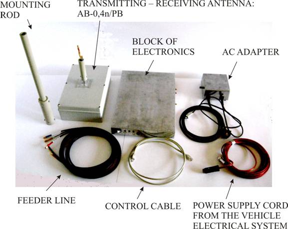
Fig. 1. Components
of the GPR "Odyag-4".
4. Specifications
The sounding pulse generator:
− Amplitude of the sounding pulse at the load 50 Ohms is more than 75.7 V;
− Repetition rate is less than 500 kHz;
− Pulse rise time is less than 0.4 ns.
The transmitting – receiving antenna:
− Operating frequency band of the transmitting and receiving parts of the antenna has a range from 0.8 GHz to 1.6 GHz;
− Attenuation of the signal passing directly from the transmitting antenna to the receiver input is more than 64,8 dB.
The strobe receiver unit:
− The level of noise at the input of the stroboscopic converter is less than 200 uV;
− The gating step is 10 ps;
− Rise time characteristics of the stroboscopic converter is less than 0.2 ns;
− The jitter is less than 3 ps.
The analog-to-digital converter has 16 bit resolution.
The control unit:
− Communication with the computer by the Ethernet port via a standard cable connection (100 Mb/s).
The scans range: 5 ns; 10 ns; 20 ns; 40 ns.
The software provides control GPR, data transfer, display the sounding results on the computer monitor in the form of the received waveforms or profile, as well as the calculation of the thickness of the structural layers of the pavement.
5. Features of GPR "ODYAG-4"
The transmitting – receiving antenna АB-0,4n/РВ implements method of complete frequency-independent isolation between the transmitting and receiving parts of the antenna system described in [5, 6]. In this method, isolation is provided by the use of the receiving antenna consisting of a pair of dipoles. Outputs of the dipoles are connected to the receiver so that at the summation of the signal received by a dipole with the signal received by another dipole, the signals induced by the transmitting antenna mutually compensate each other. In this case, the signals coming from the undersurface of the pavement are not compensated because of the time delay between them. Sum of them at the receiver input gives information about existence of structural inhomogeneities in the road surface.
Isolation (that is better than – 64.8 dB) enhances the dynamic range of GPR. Antenna that is built on this principle can also provide directional radiation and reception of radar signals.
The received signal is converted into digital code by means of the 16-bit ADC and by a high-speed (100 Mb / s) Ethernet channel is transmitted to a computer for displaying and radar data processing.
The software "SignalProcessorEx" (operating window is shown in Fig. 2) is able to accept radar data by the serial COM port or via the Ethernet as well as provide operational (real-time) display of the part of the GPR profile being sounded. This is useful for quick search of contrast inhomogeneities.
GPR receiver has two receiving channels represented by the balanced sampling converters allowing reception of reflected signals simultaneously by two spatially separated antennas.
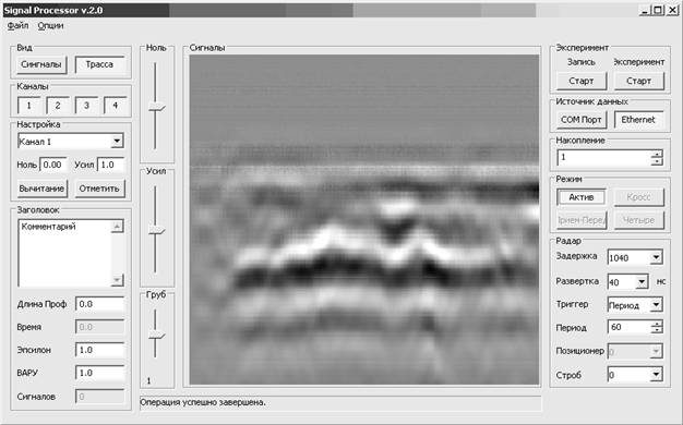
Fig. 2. Operating window "SignalProcessorEx" (Russian version) with the cross-section of the road.
Initial GPR data processing is performed by using the specialized software "GPR Proview" [7]. To accurately determine the depth of the pavement layer boundaries the software "Geovisy" is used.
Computational algorithms used in the software "Geovisy", are as follows.
1.
Based
on primary radar data using Hilbert transform [8, 9], the time delay ![]() of
signals coming from the lower boundaries and their amplitudes could be
determined. This information is input to the algorithm.
of
signals coming from the lower boundaries and their amplitudes could be
determined. This information is input to the algorithm.
2. Using the expression

where ![]() is an
amplitude of the incident signal (wave) that falls on the boundary between the
media with
is an
amplitude of the incident signal (wave) that falls on the boundary between the
media with ![]() and
and ![]() and
reflected back into n-1th medium the
and
reflected back into n-1th medium the ![]() and
then
and
then ![]() can be determined.
can be determined.
3. Next, using formulas
 , (2)
, (2)
 , (3)
, (3)
 , (4)
, (4)
 , (5)
, (5)
where ![]() are
numbers of layers,
are
numbers of layers, ![]() are the amplitudes of the
incident signals (waves) that fall on the boundaries between the media with
are the amplitudes of the
incident signals (waves) that fall on the boundaries between the media with ![]() and
and ![]() and
reflected back into
and
reflected back into ![]() th media,
th media, ![]() ;
; ![]() is
transmission coefficient from layers
is
transmission coefficient from layers ![]() th into
th into ![]() th,
th, ![]() is
transmission coefficient from layers
is
transmission coefficient from layers ![]() th into
th into ![]() th;
th; ![]() is
reflection coefficient from the boundary between layers
is
reflection coefficient from the boundary between layers ![]() th
and
th
and ![]() th back into layer
th back into layer ![]() th,
th, ![]() are
intermediate parameters used for simplification of writing,
are
intermediate parameters used for simplification of writing, ![]() is transfer function of a layer that is
multiplier at reflection coefficient
is transfer function of a layer that is
multiplier at reflection coefficient ![]() in the equation
connecting amplitude of wave reflected by the lower boundary of the certain
layer with amplitude of wave transferred back into upper layer,
in the equation
connecting amplitude of wave reflected by the lower boundary of the certain
layer with amplitude of wave transferred back into upper layer,
![]() ,
, ![]() ,
, ![]() and
and ![]() , are calculated and then, according to
(1) the
, are calculated and then, according to
(1) the ![]() could be calculated.
could be calculated.
4. Further calculations are repeated until the last of the boundaries where the only dielectric constant is determined for the base (ground).
5. Coordinates of the boundaries of layers are calculated according to the formula:
 , (6)
, (6)
where ![]() is
coordinate of the
is
coordinate of the ![]() th boundary (the
highest boundary has index 0),
th boundary (the
highest boundary has index 0), ![]() are the moments of
passing the boundaries
are the moments of
passing the boundaries ![]() th ®
th ® ![]() th that have
been found out at the stage 1,
th that have
been found out at the stage 1, ![]() is permittivity of the
layer
is permittivity of the
layer ![]() th that has been calculated at
the stages 2 or 3,
th that has been calculated at
the stages 2 or 3, ![]() is the velocity f propagation
of electromagnetic wave in the free space.
is the velocity f propagation
of electromagnetic wave in the free space.
6.
The
thicknesses of the layers ![]() are calculated using the formula:
are calculated using the formula:
![]() (7)
(7)
7. This data is stored in a file for later use.
This procedure allows to determine the value of the thickness and dielectric constant of the structural layers of the pavement at the same time and without additional laboratory experiments.
7. Tests
GPR tests (Figs. 3) were carried out on two sites of repaired roads. Measurement results are processed with the software "Geovisy" (Fig.4). The accuracy of determination of the thickness of pavement layers is demonstrated in the Table.
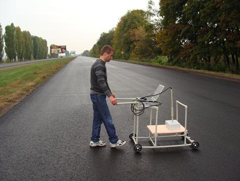

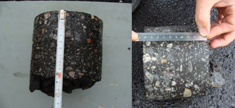
Fig. 3. Tests.
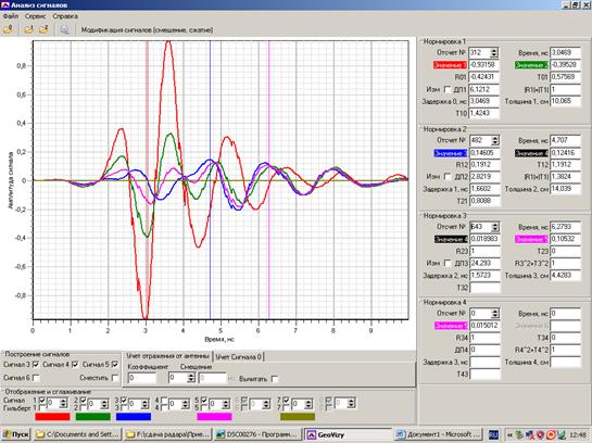
Fig. 4. Operating window "Geovisy" (Russian version). Determining of thickness of layers of the pavement.
Table. Tests results
|
Parameters |
Depth |
|
|
The actual value from the core |
Estimated value using the results of GPR surveys |
|
|
Site – "519 km" |
||
|
Package thickness of asphalt layers |
10.5 cm |
10.124 cm |
|
The thicknesses of the first and second layers |
The upper layer: 5.5 cm The lower layer: 5.0 cm |
The upper layer: 5.174 cm The lower layer: 4.9496 cm |
|
Site – "528 km" |
||
|
Thicknesses of the first, second and third layers |
The upper layer: 6.0 cm The second layer: 4.0 cm The third layer: 4.0 cm |
The upper layer: 5.989 cm The second layer: 4.09 cm The third layer: 3.915 cm |
8. Conclusion
Therefore, a ground penetrating radar and software allow user to define the thickness of the structural layers of the pavement quickly and with precision that is high enough for the roads monitoring.
1. Engineering geophysical surveys for highways. 2010. // [Электронный ресурс]. URL: http://www.geotechru.com/en/filemanager/download/446/road_ inspection. pdf
2. Ground penetrating radar for road structure evaluation and analysis. 2012. // [Электронный ресурс]. URL: http://www.geophysical.com/roadinspection.htm
3. Concrete & Pavement. 2012. // [Электронный ресурс]. URL: http://www.sensoft.ca/Applications/Concrete-and-Pavement.aspx
4. Turk A.S., Hocaoglu K.A., Vertiy A.A. Subsurface Sensing / A. Turk. - Wiley Series in Microwave and Optical Engineering, 2011. – 920 p.
5. Yu. A. Kopylov, and S. A.Masalov, and G. P. Pochanin. Method for decoupling between transmitting and receiving modules of antenna system. Patent UA 81652. Jan 25 2008.
6. Pochanin G.P. Some Advances in UWB GPR. "Unexploded Ordnance Detection and Mitigation" / NATO Science for Peace and Security Series –B: Physics and Biophysics - Edited by Jim Byrnes, Springer: Dordrecht, (The Nederland), 2009. P.223-233.
7. Golovko M.M., Pochanin G.P., Kovalenko V.O. Presentation of the results of the video pulse subsurface sensing // Radiofizika i elektronika. Kharkov: Institute of Radiophysics and Electronics NAS of Ukraine. – 2000. – 5, #2. P.134-143.
8. Krylov V.V., Ponomarev D.M. Definition of signal delay by Gilbert and methods of its measurement // Radiotekhika i elektronika. – 1980. – v.25, #1. – p.204-206.
9. Batrakov D. O., Batrakova A. G., Golovin D.V., Simachev A. A. Hilbert transform application to the impulse signal processing / Proceedings of the 5th Int. Conf. "Ultrawideband and Ultrashort Impulse Signals" UWBUSIS’2010, Sevastopol, Ukraine, September 6-10, 2010, pp. 113-115.
[*] This work was partly supported by the Russian Foundation for Basic Research and by the State Foundation for Basic Research (Ukraine) (Project № 7/12).