|
|
"JOURNAL OF RADIOELECTRONICS" N 7, 2002 |
|
HIGH RESOLUTION CAPABILITY OF ADAPTIVE
ANTENNA ARRAYS FOR COMMUNICATION SYSTEMS
G. V. Serebryakov*, e-mail:
gserebryakov@mail.ru
S. A. Tiraspolsky**, e-mail:
tiraspolsky@mail.ru
*Institute for Applied Mathematics & Cybernetics, Nizhny Novgorod.
**Nizhny Novgorod State University.
Recived 05.07.2002.
In this paper we
investigate comparison methods of different geometric configurations of adaptive
antenna arrays for communications on purpose to estimate directions-of-arrival (DOA)
of several external signals. The investigated antenna configurations have four
elements and eleven wavelengths array size. The best high-resolution algorithm
and the best array configuration are defined by numerical simulations.
Small scale fading of the mobile radio channel is normally Rayleigh distributed because of multipath propagation in wideband communications systems. The antenna receives different delayed copies (different multipath components) from the same signal. Different multipath components show usually different angles of arrival, signal amplitude as well as signal phase. The optimum performance under such propagation conditions is achieved by detecting all multipath components coherently. There are two different methods to increase the performance of the antenna in mobile radio channels. One can apply adaptive antennas [1] and use different diversity methods [2]. Adaptive antennas offer many good features against conventional antennas. By using adaptive antennas different multipath components arriving in different angles can be separated and interfering signals can be suppressed. Because of these reasons smart antennas can be used for range extension or link quality improvement [1]. In CDMA-systems, with smart antennas, less transmission power is needed and therefore multiple access interference is reduced which directly boosts the system capacity. Antenna diversity has been widely used to combat multipath fading in wireless mobile communication. Different antenna diversity methods like space diversity, polarization diversity and radiation pattern diversity are traditionally used to increase the signal quality, range of cell and capacity of the channel. Several combining methods for different diversity branches are available in literature, e.g. selection combining, equal-gain combining, maximum-ratio combining and optimum combining. Antenna diversity has some advantages compared to other diversity methods. Antenna diversity does not consume spectral efficiency but on the other hand extra equipment is required [2].
In the diversity sense the requirements for correlation properties are different than in the adaptive sense. The success of antenna diversity techniques depends strongly on the degree to which the signals on the different antenna elements are uncorrelated. The lower the correlation between antenna elements the higher in possible diversity gain with antenna array [3]. For adaptive arrays this requirement is opposite. So the problem is to choose the appropriate array configuration combined aforementioned properties for fixed number of array elements and antenna size. In this paper we compare different antenna array configurations in sense of the DOA estimation quality. The problem of DOA estimation from reverse link data (i.e. the signals of mobile units) is very important for forward link to form the appropriate beam of base station directional pattern.
We consider the reverse link of a communication system. There are total K users with identical average transmitted power P in a single cell. The interference from the neighbor cells is ignored in this analysis, considering that it is relatively small comparing with intra-cell interference. The transmitted signal for the k-th user can be written as
![]() ,
,
where ![]() is the common carrier
frequency,
is the common carrier
frequency, ![]() ,
,
![]() and
and
![]() denote
the k-th user�s binary spreading sequence, data waveform and carrier
phase shift respectively. Let
denote
the k-th user�s binary spreading sequence, data waveform and carrier
phase shift respectively. Let ![]() and
and ![]() be the chip duration and
the data bit duration, then
be the chip duration and
the data bit duration, then  is the processing gain of the spread
spectrum system. The received signal waveform at the antenna array in the
absence of multipath propagation can be expressed by one complex-valued channel
tap as
is the processing gain of the spread
spectrum system. The received signal waveform at the antenna array in the
absence of multipath propagation can be expressed by one complex-valued channel
tap as
![]() ,
,
where ![]() is a vector containing received
signal,
is a vector containing received
signal, ![]() defining
the array manifold is parameter matrix which arranges the array response
vectors as
defining
the array manifold is parameter matrix which arranges the array response
vectors as ![]() and
and
![]() is
the additive white Gaussian noise (AWGN) with variance
is
the additive white Gaussian noise (AWGN) with variance ![]() , independent from the
transmitted signals. The normalized antenna response vector
, independent from the
transmitted signals. The normalized antenna response vector ![]() can be expressed
as
can be expressed
as
 ,
,
where M is the number of antenna
elements, ![]() is
the location of m-th element,
is
the location of m-th element, ![]() is the angle of arrival of k-th
user. The spatially structured covariance matrix can be defined as follows
is the angle of arrival of k-th
user. The spatially structured covariance matrix can be defined as follows
![]() ,
,
where ![]() . In this signal model a
structured basis has been established the
. In this signal model a
structured basis has been established the ![]() part of the covariance
matrix represents the signal subspace. The complement of the signal
subspace constitutes the noise subspace. The matrix
part of the covariance
matrix represents the signal subspace. The complement of the signal
subspace constitutes the noise subspace. The matrix ![]() can
be decomposed into eigenvalues and eigenvectors. In matrix form, the
eigenvalues are
can
be decomposed into eigenvalues and eigenvectors. In matrix form, the
eigenvalues are ![]() and the eigenvectors are
and the eigenvectors are ![]() . Further, some
of these eigenvectors ideally span the signal subspace, while the others span
the noise subspace. In reality, we split the matrix
. Further, some
of these eigenvectors ideally span the signal subspace, while the others span
the noise subspace. In reality, we split the matrix ![]() into
into ![]() and
and
![]() .
Here
.
Here ![]() spans
the signal + noise subspace and
spans
the signal + noise subspace and ![]() spans the noise subspace.
Methods that work with these subspaces are often called subspace methods.
spans the noise subspace.
Methods that work with these subspaces are often called subspace methods.
The considered antenna array has four elements and size of eleven wavelengths. This is not arbitrary choice. Usually the base station antenna array has a limited number of receivers located inside limited spatial field. It is obviously that from DOA estimation point of view the array configuration with half wavelength separation between each from four elements is the best. However simultaneously this configuration is worst from diversity point of view. So the main condition to define the best antenna geometry was to use the general array size. Actually it means that we have freedom to change the location of two elements only. The antenna configurations used in simulations are illustrated in Fig.1.
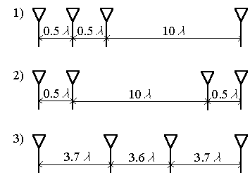
Figure 1. Investigated array configurations
We considered the following high-resolution algorithms
Minimum Variance Beamformer (MVB) method proposed by Capon [4] tries to optimize the beamforming process according to the time-varying covariance matrix. Its spatial spectrum is given by
![]() .
.
The method minimizes the power contributed by noise and signals originating from other directions than the current steering direction, while maintaining a fixed gain at the steering direction. Its performance is therefore dependent upon the input signal-to-noise ratio (SNR).
MUltiple SIgnal Classification (MUSIC) algorithm. The spatial spectrum becomes
![]() ,
,
where ![]() spans the noise subspace and
consists from M�D eigenvectors corresponding M�D
minimal eigenvalues of
spans the noise subspace and
consists from M�D eigenvectors corresponding M�D
minimal eigenvalues of ![]() (M is the number of
array sensors, D is the number of external sources).
(M is the number of
array sensors, D is the number of external sources).
Estimation of Signal Parameters via Rotational Invariance Techniques (ESPRIT) algorithm. The idea behind ESPRIT is to divide the array in two equivalent subarrays separated by a known displacement D. The DOA estimates are then angles of arrival with respect to the direction of D. For presented array configurations 2 and 3 (see Fig.1) we can split the array into two subarrays (two elements in each subarray) separated by distance half of wavelength (for configuration 2) and 11/3 wavelength (for configuration 3). Due this specific feature we cannot apply ESPRIT to array configuration 1.
The total least-squares ESPRIT algorithm for DOA estimation is as follows:
- Obtain a covariance matrix estimate
 from
the despreaded data. Here
from
the despreaded data. Here  is the received signal vector at
the antenna array, where
is the received signal vector at
the antenna array, where  and
and  represent received
signals at the first subarray and at the second subarray respectively.
represent received
signals at the first subarray and at the second subarray respectively. - Compute the eigendecomposition of
![]() ,
,
where ![]() is matrix consisting of eigenvalues
of
is matrix consisting of eigenvalues
of ![]() and
matrix
and
matrix ![]() consists
of eigenvectors of
consists
of eigenvectors of ![]() . Here M is the number of array
elements. We assume that
. Here M is the number of array
elements. We assume that ![]() .
.
- Obtain the signal subspace estimate by choosing the first L eigenvalues corresponding to the L sources of signals
![]()
and partition of ![]() as
as
![]()
- Compute the eigendecomposition of the 2L 2L matrix
![]()
- Partition V into L L submatrices

- Calculate the eigenvalues
 of the matrix
  (i
= 1, �, L).
(i
= 1, �, L). - Estimate the DOA
 ,
,
where d is the distance between
contiguous antenna elements, ![]() is the carrier frequency, c is
the speed of propagation.
is the carrier frequency, c is
the speed of propagation.
Unfortunately aforementioned high-resolution algorithms work only if the number of sources is less than the number of array elements. In mobile communication systems, the number of user signals will far exceed the number of antenna elements. In order to use high-resolution method in application to CDMA systems, it is possible to correlate the array outputs with the pseudo noise (PN) code of the desired user to despread the desired signal. Due to the good characteristics of the PN code, the data can be considered as consisting of one signal only and noise after despreading. This allows us to use aforementioned methods.
To demonstrate the performance of high-resolution methods in a CDMA system, computer simulations were performed. The data transmission rate for each user was 9600 bits/s and the transmission bandwidth was W = 1.25 MHz. We set all received signal powers equal, i.e. assume perfect transmit power control. Each user was assigned a unique spreading sequence of length 127, so the processing gain N = 127. It means that 100 users correspond to input SNR per antenna approximately equal to 0 dB. Actually for real communication situation the input SNR lies in range [� 4 dB, 4 dB]. The true DOA was 30 degrees. The received covariance matrix was calculated using by 500 samples. For simulation we used 1000 different realizations of random channel. The same channel realizations were used for all antenna configurations. As a consequence there is no statistical fluctuation in the results of different array configurations. The mean value and standard deviation (STD) of DOA estimation were calculated for three high-resolution methods and three array configurations for different values of input SNR. Mutual coupling effecting the signal correlation between antenna elements was not taken into account. The intensive numerical simulations showed that for Minimum Variance Beamformer method and MUSIC the array configuration 1 is the best (see Fig.1). For ESPRIT the configuration 2 is the best. Figure 2 shows the dependence of standard deviation of DOA estimation on input SNR for different resolution algorithms using the best array configuration.
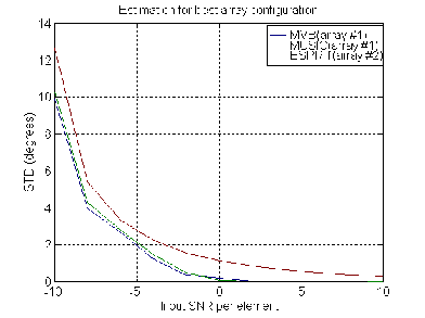
Figure 2. Different high-resolution algorithms for best array configuration
As seen from Fig.2, MVB and MUSIC algorithms have practically same resolution properties. However despite to the fact that MVB method and MUSIC demonstrate the better results in comparison with ESPRIT we would not recommend these algorithms for application in real communication systems due the following reasons:
1. ESPRIT is more effective from computational point of view;
2. In contradistinction to ESPRIT, MVB and MUSIC have additional false peaks in spatial spectrum.
In particular, Fig. 3, 4 show the typical spatial spectrums of MUSIC (Fig. 3) and MVB method (Fig. 4) for array configuration 1.
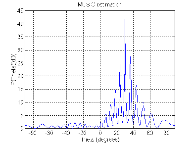
Figure 3. MUSIC spatial spectrum for array configuration 1
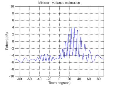
Figure 4. MVB spatial spectrum for array configuration 1
We can see the presence of false peaks in spatial spectrum. In real communication applications its peaks may prevent to good DOA estimation. At same time ESPRIT produces signal parameter estimates directly in terms of eigenvalues and has no such disadvantages. So, it seems that in according with these simulations the best resolution properties were achieved by using ESPRIT for array configuration 2.
In this paper we do not consider the effects of multipath but the approach can be used to include a multipath model taking into account the Geometry-based Stochastic Channel Model (GSCM) [5], for example.
5. CONCLUSIONS
A comparison of the performance efficiency was made for three different antenna configurations to compare their DOA estimation quality. The considered antenna configurations had the same number of elements (four) and the same general array size (eleven wavelength). We suppose that the best DOA estimation capability was achieved for array configuration 2 using ESPRIT and the worst result for the array configuration 3, respectively.
6. ACKNOWLEDGEMENTS
This work was supported in part by RFBR grant No. 02-02-17056.
7. REFERENCES
-
J. Liberti, T. Rappaport, Smart Antennas for Wireless Communications, New Jersey, USA: Prentice Hall, 1999.
-
R. Vaughan, J. B. Andersen, "Antenna diversity in mobile communications," IEEE Trans. on Vehicular Technology, Vol. 36, No. 4, November 1987, pp.149-172.
-
W. Jakes, Microwave Mobile Communications, New York, USA: John Wiley & Sons, 1974
-
J. Capon, "High-resolution frequency-wavenumber spectrum analysis," Proc. IEEE, Vol. 57, No. 8, 1969, pp.1408-1418.
-
J. Fuhl, A. F. Molisch, E. Bonek, "Unified channel model for mobile radio systems with smart antennas", IEE Proceedings of Radar, Sonar and Navigation, Vol.145, No.1, February 1998, pp.32-41.