| "ЖУРНАЛ РАДИОЭЛЕКТРОНИКИ" "JOURNAL OF RADIOELECTRONICS" N 6, 1999 |
MULTI-BAND ELECTRONICALLY SCANNED ANTENNAS OF CENTIMETER AND MILLIMETER WAVE RANGES
Moscow State Technical University named after Bauman,
5, 2-Baumanskaya Str., Moscow 107005, Russia
Received June 23, 1999
Foundations and principles of radio lenses constructing of centimeter and millimeter wave ranges with controlled refraction index, combining the quality of phased array antennas with optical devices are stated. Possibilities of the electronically scanning with wide-angle sector and high gain are maintained. Construction principles of scanning antennas with controlled lenses, combining the quality of phased array antennas with optical devices, are stated. Possibilities of electronically scanning with broad angle sector and high gain are maintained. Some examples of construction of antennas millimeter range of waves are listed here.
In millimeter wave range research results carried out with purpose of antenna creation satistuing to next requaries are represented:1. INTRODUCTION
Complexity of a design and technology of phase shifters for phased array antenna constrains the extension of areas of their application and creation of phased array antenna of millimeter range waves. One of overcoming paths of these difficulties is creation and application for control a beam devices with high degree of integration and use of new technical solutions, different from the used in phased antenna array.A series of advantages in comparison with multi-element phased array have lenses with the electronically controlled refraction index, application of which allows considerably to simplify a design and manufacturing technology of millimeter wave range antennas with electrical beam scanning in wide angle sector.
Controlled lenses are constructed on the basis of medium with electronically controlled refraction index, such as ferrite, liquid dielectric, having metallic and dielectric particles in suspension and metallic delay structures. The creation of such antennas requires solution of problems both in the theoretical area and in manufacturing of new element units in the antenna engineering. In a series of cases, mainly at use for their construction of solid environments, controlled lenses have many commons with deflectors widely used in optical systems. Refracting (but not focusing) devices with the controlled refraction index, called deflectors, rather long time are used in optics. In a small angle prisms under effect of an external electrical field the refraction index varies simultaneously in a whole volume of prisms. In ultrasonic light deflection system (in a Bregg’s prisms) the refraction index under effect of an ultra sound varies according to the harmonic law and thus diffraction grating creates. It is represented tempting to use for control a radio beam the principles incorporated in indicated optical devices. However similar devices in case of necessity of electrical scanning by a beam at radio band with wide-angle sector would have unacceptable large sizes, in that one can easy convinces by making elementary calculations. It presents and series of other reasons, stipulated first of all by the dielectric characteristics used in radio band, on which direct transferring principles of control by an optical beam in radio band is not possible.
The first work contained the information about rather incomplete scanning radiator of the array antenna with controlled lenses, made as located in apertures horn ferrite prisms, was published in 1968 [2]. In 1975 the description of similar principle of the centimeter wave range antenna scanning in one plane was published [3]. Disadvantages of such antennas (small sector of beam scanning and the high losses) are stipulated by the fact that while scanning a phase along aperture varies according to the linear law and adjustable phase shift in many times exceeds 360o. A radiator of a transmitting active phased array antenna with high-radiated pulse and average power is shown on Fig.1. The radiator contains a ferrite lens, excited by a pyramidal horn. The lens is a system of ferrite rods immersed into liquid dielectric. Water radiators make removing of the heat from the side areas of the lens. The sector of beam scanning is 90o x 90o.
Rather detail theoretical and experimental researches of controlled lenses were made in 1977...1987 years and have allowed to determine principles of construction of lenses, scanning at wide angle sector, and to evaluate their limiting characteristics [1]. The models of the antenna with controlled lenses of dipole structures and ferrite rods permitting to form two independently controlled beams with orthogonal polarization where offered and realized. The further activities in main were concentrated on the development of design and production process of lenses for millimeter wave range antennas [5, 6, 7].
In considered below radiolenses, as well as in optical deflectors, diffraction grating is formed appropriate to specific angle parameters of a beam deviation, basic of which is the period of a refraction index change at orthogonal direction to extending in a lens electromagnetic wave. Basic feature of considered system is availability strong distributed connection on high-frequency electromagnetic field between areas of a lens, distinguished by refraction index. Such distributed connection in significant degree determines the characteristics of controlled lenses. It is necessary to find relations, linking major characteristics of refractive medium (factor of distributed connection, activity) with geometry of a lens and characteristics of materials. With the registration of these relations it is necessary to formulate principles of technical implementation of controlled lenses and determine their limiting characteristics.
The theoretical analysis of the electrical characteristics of controlled medium and lenses made on their basis has allowed to formulate the requirements to controlled medium depending on a type of controlled lenses, sector of beam scanning and range of operational frequencies, and also to make optimization of a controlled lens in general [1].
2. GENERALIZED CHARACTERISTICS OF CONTROLLED REFRACTIVE MEDIA
As generalized parameters describing controlled medium are used a coupling coefficient C and activity Р and g o - coefficients slowing phase speeds of main types waves ("even" and "odd") in controlled medium with identical in whole volume value of refraction index equal to the average value of controlled medium. The "even" wave is understood as a wave with phase shift y =0 on period of a system d, to the "odd" wave corresponds y =p . The slowing g are determined by the rations of waves phase speeds in considered medium to waves phase speeds in external area. For solid homogeneous medium with relative permittivity e pursuant to entered determination slowing phase speed plane homogeneous "even" wave numerically equally to an refraction index and slowing "odd" wave. For refractive medium with a controlled dielectric permittivity at calculations average value is used к=0.5(e max+e min). For ferrite media calculation is conducted from value of a dielectric permittivity of ferrite e f. The coupling coefficient C characterizes a degree of interaction electromagnetic fields between adjacent areas of media, distinguished by a refraction index. The increasing connection (i.e. increasing coefficient C), make the law of a refraction index more complicated inside a lens, ensuring required declination phase wave front on an output and, there fore, radiation direction.In the ratio, determining activity media values P, g e+ and g e— is limiting values (maximum and minimum) slowing phase speeds of the lowest type waves at two extreme condition controlled media, appropriate, for example, two directions magnetization of ferrite elements or two state of semiconductor keys (closed and disconnected) in artificial medium from controlled wire structures. Outcomes of theoretical and experimental researches of controlled media characteristics of periodic structures from ferrite rods show, that their characteristic values C/P lie within the limits of 0.05...0.10. For solid ferrite medium this parameter has values 0.4...0.7, and for liquid medium 0.2…0.3. Parameters of controlled medium C, P, e and ratio C/P determine a structure and sizes of a controlled lens.
3. STRUCTURE OF A CONTROLLED LENS
In general case the inhomogeneous controlled lens must perform two main transformation of waves passing through it: to transform a wave radiated by a horn feed to a wave with a plane phase front (i.e. to execute a focusing) and then change declination of the plane phase front by a required angle. Thus both surfaces of a controlled lens can be plane and the lens in this case is a layer of inhomogeneous dielectric. We will consider just such lenses.The controlled lenses with plane surfaces can be divides by the refraction index change law by two main groups: longitudinally homogeneous and longitudinally inhomogeneous lenses. In the both groups the refraction index varies by a periodic law over cross-section. The longitudinally-inhomogeneous lens are easier to realize because the refraction index in the longitudinal direction can be varied by steps (discontinuity) at the transition from one layer to other (multilayer lens).
We shall consider a controlled lens, excited by a wave with a plane phase front. In general case such controlled lens consists from several layers distinguished by the refraction index change law. We shall consider transformations plane homogeneous wave I0 to a wave with inclined phase front I+1. A functional of a two-layer lens (the Fig.2) is explained as follows.
Plane homogeneous wave, extending along axes of lenses, is transformed to a wave with inclined phase front in two stages. The first layer 1 (next to the focal device) transformed the falling wave into two plane homogeneous waves I+1 and I-1, which spread under differently sign angles. Combination of these waves on boundary of section of layers 1 and 2 gives a "odd" wave. Then layer 2 performing the part of deflector offered by Bregg change the direction (only the sign of the angle) of one these waves. The indicated transformations of plane waves correspond to scheme: I0® I+1+I-1® I+1. A necessary condition of such transformations: period D of change of a refraction index in the first layer owes to be twice more than period of change of an index in second layer. The order of arrangement of layers has basic value. At the refraction index change saw tooth law, as have shown results of theoretical researches, relative arrangement of jumps of an refraction index in layers 1 and 2 depends on a ratio between values I-1 and I+1 and varies at change of a angle scanning of a beam.
In general case the lens scatters a wave into a set plane waves, i.e. electromagnetic field in the output of lens has complex spectral structure of spatial harmonics. The smaller part of energy of the exciting field goes into parasitic spectral components, the greater the lens efficiency is. The indicated criterion is decisive in the process of lens optimization consisting in determination of the number of layers and the refraction index change law. At large angles of beam deflection the refraction index change law become significantly more complex. In particular, it becomes necessary to compose the lens of greater number of longitudinally homogeneous layers. It requires application of more complex control algorithms for control of the refraction index, but practically does not complicate the lens design.
The number of longitudinally homogeneous layers is determined by sector of beam scanning and generalized parameter C/P, where C is distributed coupling coefficient characterizing the medium, and P is coefficient of activity of the media. Lets consider some requirements to the refraction index change law n layers of lenses, revealed in the result of analytical studies. At first, the refraction index change law in single-layer lenses significantly differs from a liear sawt-wise one. Secondly, with increase of the angle of phase front inclination at constant lens thicness, one should reduce the difference between nmax and nmin and increase the average value of n. For example, for ferrite lenses the best difference D =nmax-nmin decreases about 1...2 times with increase of the beam deflection angle from 10 up to 40o.
The two-layer lenses are necessary for applying when controlled media is characterized by large value of a distributed connection coefficient, owing to that single-layer lenses are ineffective because of field distortions in the aperture at large deviation angles of a beam.
On Fig.3 boundaries between areas where rather effectively work elementary single-layer lenses (N=1) with the refraction index change law, close to saw tooth, two-layer (N=2) and three-layers (N=3) lens are shown. Boundaries correspond to limiting gain reduction of a lens from distortions of a field in its aperture about 1.1,5 dB.
Period of an refraction index change in layers of a lens (see Fig. 2) is determined by a angle of beam deviation Q m, and if reset of a phase happens on reaching value 2p , than D=l /sinQ m. If controlled media is a periodic system, for example, from ferrite rods, period d of rods arrangement is determined the same as period of arrangement radiators in a phased array. It is stipulated by necessity of occurrence exception of the minor diffractional maximums in the pattern because of availability inevitable modulation of amplitude distribution of a field in lens aperture with period, equal to period of arrangement of controlled media elements. Lens with the exciting device and with a free space are adjusted or with the help of systems of adjusted cones (if the controlled media represents a periodic system from lines of surface waves), or quarter-wave layers, the parameters of which are determined from value n for a layer controlled media.
In the centimeter wave band and in a long-wave part of the millimeter band (Ka-band) there used periodic structures consisting of lines of surface waves with a controlled propagation constants. Such lines, for example, are longitudinally or transversally magnetized ferrite slices and rods. For constructions of scanning antennas of the millimeter waves range (the band V and W) the most appropriate are solid controlled media in the form of liquid dielectric, having metallic or dielectric particles in suspension, and ferrites.
On Fig. 4 the graphics describes the limiting values of a relative gain (G/G0) in sector of scanning and level of side lobes Psl in pattern of a lens of solid controlled media with average value of an refraction index 1,5 (for example, liquid dielectric). By vertical stroke-dot lines are designated approximate boundaries of sectors of scanning of lenses with number of layers equal 1,2,3 and according refraction index change law. Dot line is shown gain of one layer lens with saw tooth law of quadrate change of refraction index. In the denotations of the graphics, describing the laws changes of an interval D =nmax-nmin, the indexes correspond to numbers of layers.
4. CONTROLLED REFRACTIVE MEDIA
The media of this type represent periodic structures of ferrite rods, the axes of which are oriented in parallel axe of a lens. The magnetization of ferrite elements one can realizes as in a longitudinal direction with the help of coaxial with them coils, and in a transversal direction by passing of a current on conductors, placed along their axes.On Fig. 5 values P (solid lines) and C (dashed) are shown for a periodic system of transversal-magnetized (path 2) and longitudinal-magnetized (path 1) ferrite rods. The analysis of equations, describing at a wide band of wave lengths activity of medium as periodic systems with various geometrical parameters shows, that in area d=(0,6...0,7)l the value P varies in rather small limits. It creates the premises for construction wide band controlled lenses of such media [1]. Maximum values of activity are reached at diameters of transversal-magnetized ferrite rods a=(0,25...0,28)l . It is also the fact, that with reduction distance between rods (d<0,6l ) at transversal magnetization the activity quickly decreases. Sharp activity reduction at reduction of rods diameter or period of a system coincides the beginning of fast increase coefficient of connection. For systems of ferrite rods in the field of small diameters a and periods d the coupling coefficient essentially depends on polarization of a wave. The values C and P are practically identical at arrangement of rods units of rectangular and hexagonal grids, if space coefficients Ks=p a2/S1, are equal; here S1- cross sectional area on unit rod.
Liquid and semiconductors are concerned to solid medium with a controlled refraction index. The change of a refraction index of ferrite medium happens under applying of a magnetic field. It is known, that at longitudinal magnetization in such medium effect of polarization planes rotation is observed. In this connection ferrite lenses with longitudinal magnetization (along an optical axis of a lens) work on waves with circle polarization. Polarization distortions of a field on an output of such lenses are away only in the case, if the refraction index in layers varies on the harmonic law. At change according to the saw tooth law the distortions can be rather essential. At transversal relatively a direction of distribution of an electromagnetic wave magnetization control of refraction index is also possible, if the extending electromagnetic wave is polarized in planes, orthogonal to a direction of magnetization. In [4] characteristic artificial fluid dielectric with suspended smallest metal particles are description. For working frequencies, appropriate to millimeter range of waves, in quality liquid dielectric are used n-nonane and other similar substances. The metal particles have the shape of stretched ellipsoids. In the absence of any external effects they are oriented chaotically and effective dielectric permittivity of such artificial dielectric is close to dielectric permittivity of liquid (e =2). Orientation of metal particles is reached with the help of external electrical field. If the majority of particles are oriented by large axis along a direction of electrical field vector of electromagnetic wave, effective dielectric permittivity increases. The refraction index can be operated with the help of electrodes systems, diving through dielectric conductors or by passing ultrasonic waves. For preventing sticking of metal particles together fluid owes to circulate, and the controlling voltage should be alternating.
5. ANTENNAS WITH CONTROLLED LENSES
Some examples of construction relating to antennas of the centimeter and millimeter wave ranges are listed here. 5.1. Two-band antenna with a controlled lensFig.5 represents a two-band antenna with a controlled lens made in the form of a periodic system of transversally-magnetized ferrite rods. The antenna operates in two frequency bands: in band F1 it forms one scanning beam, and in band F2<0.5F1 it forms one or more of non- controllable beams. The frequency F1 corresponds to the K-band (12...27GHz); the scanning is implemented within the sector 70o. The operating frequency band of the antenna in the K-band was more than 25%.
The ferrite rods forming the controlled medium are fixed directly on the wall of an H-sectorial horn (in Fig.6 this wall is elevated). Conductors of the system controlling magnetization of the ferrite rods are located in grooves, cut in the horn wall under the ferrite rods along their axes. The wall of the horn is a part of the iron circuit and provides short circuit of magnetic flows going through the rods. The conductors of the control system are connected through a hole in the horn wall to distributing system made as a printed circuit board with chips placed on it located on the external surface of the horn walls. The matching of a lens is provided by conic tapers made on both ends of ferrite rods. In the H-sectorial horn there is placed a metal-air lens made as a convolution with a parabolic phase corrector.
The capability of such adjustment is created due to division of conductors, located under ferrite rods, on four distinguished in length sections. Longest section (length of which is about 1,5l ) magnetizes to saturation segment of ferrite rod of same length and allows to create differential phase shift 180o. Two other sections of smaller lengths allow to create phase shifts 90o and 45o. Additional the fourth section serves for correction of phase distribution by the registration of mutual influence of rods, creating different phase shifts. Thus, maximum phase shift, created by each rod at full magnetization and at absence of mutual influence of adjacent rods is approximately 330o . Section, creating phase shifts 180o, are located on the part of the device exciting a lens. Phase distribution of a field in aperture of such lens is close to sawtooth with "reset" of a phase on size, divisible 2p
Effective vending of warm from ferrite rods, ensured at the expense of their contact to a wall of a horn, allows to use such lens in radiators with a high level of mean power. Yet one essential advantage of a considered lens in comparison with lenses with gradient refraction index change law, stipulated by periodicity of refraction index change law, consists of absence of any basic limitations on the sizes of emanating aperture.
5.2. Antenna with a ferrite lens of a reflective typeAn antenna with a ferrite lens of a reflective type is shown on Fig.7. The antenna consists of a feed horn and mirror with controlled reflection coefficient. The mirror formed by multilayer slices touching each other by their sides. The phase of the electromagnetic wave from reflected from the slices varies in the plane of aperture according to the law providing focusing and deviation of beam. Such a device is a reflective lens with a controlled refraction index. Each of slices represents a multilayer design including a screen with controlling plate, and a matching transformer in the form of a dielectric plate. By drilling the phase-controlling plate to partial depth, a periodic lattice is formed which consist of cylindrical rods and magnetic circuit.
The same scanning device model functioning at the whole 35GHz - 70GHz frequency range has been made and tested. The module is constructed in form of monolithic ferro-magnetic block with 100 x 100mm aperture size. Sector of scanning at 37GHz is 60° x 60° , at 60GHz – no less than 40° x 40° , at 70GHz – no less than 30° x 30° . Root mean square deviation from calculated phase distribution on the aperture is no more than 12° . Time of change of beam direction is 10 mcs at energy of switching (calculated on 1cm2 of the area of aperture) is no more than 40mcJ.
Constructed block is intended for making controlled reflection coefficient lenses for multy-frequencies antennas. Used block making technology allows constructing such antennas for the frequency range up to 120…140GHz.
5.3. Antenna with a controlled lens made from a liquid dielectric
The controlled lens [1] is made as broad in an H-plane cavity with dielectric walls, filled with suspension. A cavity is installed in aperture of an H-sectorial horn and executes functions of a focusing lens and scanners simultaneously. For the control of suspension dielectric permettivity the matrixes of managing electrodes are put on the upper and lower broad walls of a lens by methods of printed technology, jointed with a control system the multipin plug. Control refraction index change law in such lens implements by supply of alternating voltage with a constant amplitude on appropriate (depending on required law) electrodes. The lens is shielded by a layer of metallizing on the sidewalls and is matched with a free space with the help of dielectric transformer. For preventing a settling of metal particles the alternating control voltage and constant pumping of suspension is used.
In the made and tested at frequency band W lens control electrodes are situated with period about 0.65l in three series (three layers), permitting to discretely change a phase on p ; 0.5p and about 0.25p . The layer, changing a phase on p , is located closer to the feed horn. The antenna scans by a beam in sector 50o.
The same as in optical the deflectors change of an index refraction of dielectric lenses can implement with help of passing through them of ultrasonic waves. The refraction index change law as in space and in time determines control efficiency of a beam with the help of such devices. Optimization of the refraction index change law was made with scanning lens, representing a two-layer slice, in layers of which the refraction index is determined by a spectrum of frequencies, passed through them ultrasonic waves. Algorithm of optimization provides definition of thickness of layers at specific values of modulation coefficient and selection of the refraction index change law in each layer so that a maximum of spatial harmonic of a diffracted field was provided, appropriate to specific angle of beam deviation. It was determined, that for scanning sector 40o...60o and more in a spectrum of controlling ultrasonic signal should be contained 5...7 harmonics with appropriate amplitudes.
6. CONCLUSION
The lenses made on the basis of medium with electrically controlled refraction index are a new type of antennas that can scan in a wide angular sector. By their principal electrical characteristics they, potentially, are no worse than the phased array antennas, and by their wide band capabilities they exceed the phased arrays. The controlled lenses can be realized at the whole millimeter wave range. They have a simpler design in comparison with phased array antennas, and are characterized by a high degree of integration of elements in the process of production.
REFERENCES
FIGURES
Fig.1. Radiator of transmitting active phased array antenna
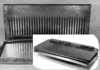
Fig.2. Two-layer lens.
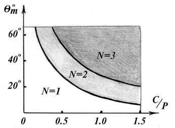
Fig.3. Number of layers of controlled lens
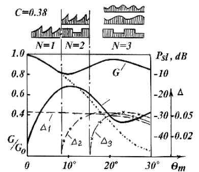
Fig.4. Limiting values of characteristics of lenses of solid controlled media.
Fig.5.Characteristics of controlled media:
1) P, longitudinal-magnetized ferrite rods, ef =10, d=3a, mz =0.25.
2) P, transversal-magnetized ferrite rods, ef =10, d=3a, ma =0.25;
3) C, longitudinal-magnetized and transversal-magnetized ferrite rods.
Fig.6.Two-band antenna with a controlled lens
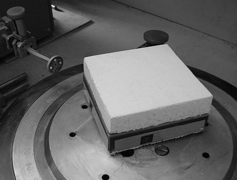
Fig. 7. An antenna with a ferrite lens of reflective type.
Author:
Bei Nikolay Arsenyevich, e-mail: bei@mx.bmstu.ru