Modelling and analysis of bow tie nanoptenna
Shruti Taksali, Sandhya Sharma
Suresh Gyan Vihar University, India
Received May 13, 2013
Abstract. This paper focuses on the optical characterization of nano optical antenna structure which is termed as nanoptenna. Generally, the dimensions of antenna are of the order of the radiation wavelength and therefore creates the need of designing antenna at nano scale for visible portion of optical spectrum (400nm-800nm) i.e. nanoptenna. When two triangular pieces of gold are placed side by side with the apices facing one another, the capacitive coupling between them will generate even higher fields than those generated by an isolated particle. This Bowtie structure is preferred here because it offers extraordinary field confinement and a broadband spectral response as it contains Moreover; the enhanced field via the strong light spot produced by the nanopntenna is highly dependent on its structure.
Keywords: nanoptenna, bowtie, nano, optical spectrum, antenna.
1. Introduction
The term ‘Nanoptenna’ is derived from the combination of the technologies such as antenna, nanotechnology and optical communication, which indicates the antenna as a specially designed nano device for communication at optical frequencies.
Nanotechnology is defined as the application of scientific knowledge to control and utilize matter at the nanometre scale (about 1–100 nm). At this scale size related properties and phenomena can emerge .Because diffraction limits the confinement of propagating radiation to roughly half a wavelength, the length scales over which optical fields can be manipulated traditionally lie outside the size range of interest to nanotechnology. It is often possible to spatially separate the nanoscale building blocks and to study their physical and chemical properties by using standard spectroscopic techniques [1-7]. Until now, antennas have been designed for communication at radio wave and microwave frequencies but not at optical range, which includes the visible portion of light spectrum. The advent of nanoscience and nanotechnology provides access to this length scale with the use of novel top-down nanofabrication tools (e.g. focused ion beam milling and electron-beam lithography) and bottom-up self-assembly schemes[8-10]. Bowtie nanoptenna is designed to improve the optical mismatch between nanoscale objects and light. Near the tip, the bow tie antenna with a gap of around 20 nm can reach an intensity enhancement of more than 1000. Therefore, bowtie structure is preferred `because it allows the enhancement of input signal with extremely high intensities in the gap which is well suited for broadband transmission and reception. In other words, it offers both extraordinary field confinement and a broadband spectral response. Antenna theorypredicts that electric fields (E-fields) are enhanced in close proximity to sharpened metal points with a radius of curvature much smaller than the incident illumination wavelength, the so-called lightning-rod effect that has been recently applied at optical frequencies, producing lateral resolution approximately the curvature of the point [11]. The E-field enhancement in aperture less near-field systems has been exploited to produce an ultra-small, ultra-intense light source that has applications in high-density optical storage, high-resolution optical imaging, and laser spectroscopy, including enhanced fluorescence and Raman scattering [12,13]. Compared to the other antenna designs, bowties seem to offer the largest near-field enhancements and the smallest spatial extent for the field, that is, a single sharp optical spot most of the electromagnetic energy is localized in the gap of the antenna. This property of bowties is crucial for applications requiring a very intense spatially confined optical spot. The bowtie nanoptenna consists of two triangular pieces of gold, each about 75 nanometres long, whose tips face each other in the shape of a miniature bowtie. The device operates like an antenna for a radio receiver, but instead of amplifying radio waves, the bowtie takes energy from an 830-nanometer beam of near -infrared light and squeezes it into a 20-nanometer gap that separates the two gold triangles. The result is a concentrated speck of light that is a thousand times more intense than the incoming near-infrared beam Because the shortest wavelength of visible light is 400 nanometres, a conventional microscope cannot resolve objects 200 nanometres or smaller. But the bowtie antenna produces an optical spot that's 20-nanometers wide, so we're improving the resolution by a factor of 10 [1].The enhanced fields are specifically important for process involving sum frequency generation since the resulting high photon densities increase the probability of photon combination. Therefore, optical characterization is done to understand the nature of nanoptenna resonance, near field distribution and possible applications. The fabrication of optical antenna structures is an emerging opportunity for novel optoelectronic devices.
2. Theory
We have used nano toolkit for this work whose design parameters are described as below.
For the characterization, we have used a Gaussian pulse as a source which is a wave packet of a specified width incident on the antenna at t=0.We have chosen its central wavelength as 600 nm which is the wavelength corresponding to the central frequency of the pulse. Its temporal width is full width half maximum duration of the pulse, which is chosen as 2 femtoseconds. The duration i.e. the number of widths characterizes the finite time of emission of the pulse. Thus the pulse is at zero amplitude at t=0,t=duration and the peak occurs at t=duration/2.
Gold has been used as a basic particle for nanoptenna due to its inherent optical properties and has a dielectric constant of 5.The top substrate is the dielectric layer having a dielectric constant of 2.2 directly beneath the bowtie antenna and the bottom substrate is the dielectric layer with a dielectric constant of 2 beneath the top substrate layer.
The bowtie nanoptenna consists of two triangular pieces of gold, each about 75 nanometres long, whose tips face each other in the shape of a miniature bowtie .As we know that perfect bow tie edges are impossible to fabricate; the edges are rounded with a specified radius of curvature. We have chosen cell size buffer as 45 nm, which is a buffer between walls of computational cells, and bow tie structure so that perfectly matched layer (PML) can never interfere with near field bowtie dynamics. The thickness of PML is chosen as 28nm, which is a boundary condition, that triggers absorption all radiation impingent on the walls of the computational cell, and therefore we have the following design parameters.
· Triangle altitude=76nm
· Radius of curvature=14nm
· Thickness=24nm
· Flare angle=30’
3. Main Thrust of the paper
For weak excitation intensities, the radiation rate Ãrad can be expressed as
![]() (1)
(1)
where![]() is the
excitation rate and
is the
excitation rate and ![]() is the quantum yield. Both
is the quantum yield. Both![]() and
and![]() depend on the antenna’s properties and the separation, z,
between antenna and molecule.
depend on the antenna’s properties and the separation, z,
between antenna and molecule. ![]() corresponds
to the radiation efficiency.
corresponds
to the radiation efficiency.
The data demonstrate that, as the gold
particle is brought closer to each other, the fluorescence emission rate first increases
and then is suppressed. The initial fluorescence enhancement is due to the
antenna effect of the gold particle. The excitation rate![]() ,
increases because of the enhanced local fields near the nanoparticle. However,
for separations shorter than z = 10nm, the radiation efficiency
,
increases because of the enhanced local fields near the nanoparticle. However,
for separations shorter than z = 10nm, the radiation efficiency ![]() decreases
rapidly as more and more of the energy is absorbed in the gold nanoparticle.
Touching pairs of metallic nanoparticles have a strongly red shifted scattering
spectrum when light is polarized along the pair i.e. parallel to the axis that
joins the nanoparticle centres, but the spectrum resembles single particle
scattering when the polarization is perpendicular to the particle pair.
Therefore, strong gap dependent spectral shifts are evident for bowties pumped
along their axis. For the spectra acquired when the excitation light is
polarized perpendicular to the bow tie long axis, the peak scattering
wavelength varies little with increasing gap lengths, though the scattering
intensity decreases with increasing gap sizes. Hence, we have chosen
polarization parallel to the bow tie axis.
decreases
rapidly as more and more of the energy is absorbed in the gold nanoparticle.
Touching pairs of metallic nanoparticles have a strongly red shifted scattering
spectrum when light is polarized along the pair i.e. parallel to the axis that
joins the nanoparticle centres, but the spectrum resembles single particle
scattering when the polarization is perpendicular to the particle pair.
Therefore, strong gap dependent spectral shifts are evident for bowties pumped
along their axis. For the spectra acquired when the excitation light is
polarized perpendicular to the bow tie long axis, the peak scattering
wavelength varies little with increasing gap lengths, though the scattering
intensity decreases with increasing gap sizes. Hence, we have chosen
polarization parallel to the bow tie axis.
|
a |
b |
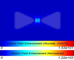
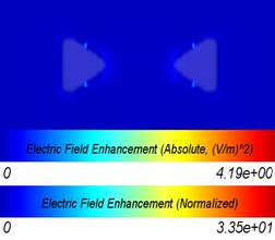
Figure 1. The simulation image of the electric field enhancement distribution in a bow tie antenna structure for gap a.) z=20 nm .b) z=120 nm.
From the Figure 1 it is very clear that by varying gap between the two triangular pieces of gold i.e. less than 100 nm and greater than 100 nm , we get different electric field enhancement for red and blue spectrum.
|
a |
b |
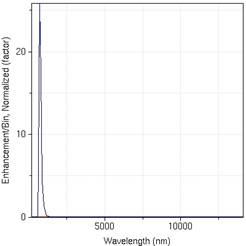
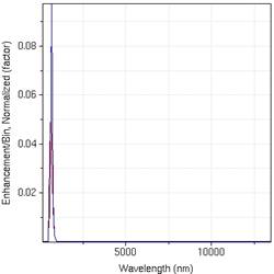
Figure 2. The plot of wavelength against normalized enhancement for various gaps a.) z=20 nm, b) z=120 nm. Thus, for a gap greater than 100 nm the red spectrum shifts with increasing gap lengths.
|
a |
b |
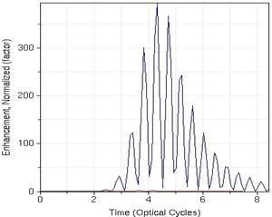
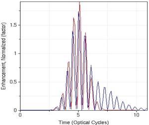
Figure 3. The plot of optical cycles as a function of normalized enhancement factor for various gap a)z=20 nm b).z=120 nm
Optical excitation of the bowties excites the Plasmon resonance of the structure, which may be sensed in the wavelength dependence of the scattering spectra.From the Figure 2 for a gap size less than 100 nm, the blue spectrum shifts from the peak wavelength to a lower wavelength as gap size increases. However, at gaps larger than 100 nm, the red spectrum shifts with increasing gap lengths The bowtie antenna supports multiple resonances in the examined spectral range, leading to a rather broadband response. Additionally, the slope of the plot is much larger for small gaps than for large gaps. Thus, it appears that each constituent triangle of a bowtie antenna can be thought of as a collection of small-coupled dipoles, arranged in a finite two-dimensional lattice.
4. Conclusion and Outlook
We had analyzed the resonant behaviour of bowtie antennas with different gap widths and concluded that the capacity of the air gap plays a dominant role in determining the resonant wavelength (λres) for small gap widths. We observed that resonant wavelength first blue shifts with increasing gap and then red shifts beyond a certain gap width. As the gold particle is brought closer to each other, the fluorescence emission rate first increases and then is suppressed. Thus, the initial fluorescence enhancement is due to the antenna effect of the gold particle.
5. Acknowledgement
The authors would like to thank the staff and management of Suresh Gyan Vihar University for their kind support in this research project.
[1]. W. Gotschy, K. Vonmetz, A. Leitner, and F. R. Aussenegg, ”Optical dichroism of lithographically designed silver nanoparticle films,” Opt. Lett. 21, 1099 (1996).
[2]. S. J. Oldenburg, R. D. Averitt, S. L. Westcott, and N. J. Halas, ”Nanoengineering of optical resonances,” Chem.Phys. Lett. 288, 243-247 (1998).
[3]. J. Kottmann, O. Martin, D. Smith, and S. Schultz, ”Spectral response of plasmon resonant nanoparticles with anon-regular shape,” Optics Express 6, 213-219 (2000).
[4]. H. Ditlbacher, B. Lamprecht, A. Leitner, and F. R. Aussenegg, ”Spectrally coded optical data storage by metalnanoparticles,” Opt. Lett. 25, 563-565 (2000).
[5]. H. Tamaru, H. Kuwata, H. T. Miyazaki, and K. Miyano, ”Resonant light scattering from individual Ag nanoparticles and particle pairs,” Appl. Phys. Lett. 80, 1826-1828 (2002).
[6]. G. Schider, J. R. Krenn, A. Hohenau, H. Ditlbacher, A. Leitner, F. R. Aussenegg, W. L. Schaich, I. Puscasu, B. Monacelli, and G. Boreman, ”Plasmon dispersion relation of Au and Ag nanowires,” Phys. Rev. B 68, 155427 (2003).
[7]. J. Aizpurua, P. Hanarp, D. S. Sutherland, M. K¨all, G. W. Bryant, and F. J. Garc´ıa de Abajo, ”Optical Properties of Gold Nanorings,” Phys. Rev. Lett. 90, 057401 (2003).
[8]. C. L. Nehl, H. Liao, and J. H. Hafner, ”Optical Properties of Star-Shaped Gold Nanoparticles,” Nano Lett. 6,683-688 (2006).
[9]. L. J. Sherry, R. Jin, C. A. Mirkin, G. C. Schatz, and R. P. VanDuyne, ”Localized Surface Plasmon Resonance Spectroscopy of Single Silver Triangular Nanoprisms,” Nano Lett. 6, 2060-2065 (2006).
[10]. H. Wang, D. W. Brandl, F. Le, P. Nordlander, and N. J. Halas, ”Nanorice: A Hybrid Plasmonic Nanostructure,”Nano Lett. 6, 827-832 (2006).
[11]. Novotony, L.; Bian, R. X.; Xie, X. S. Phys. ReV. Lett. 1997, 79,645.
[12]. Hamann, H. F.; Kuno, M.; Gallagher, A.; Nesbitt, D. J. J. Chem.Phys. 2001, 114, 8596.
[13]. Hartschuh, A.; Sanchez, E. J.; Xie, X. S.; Novotny, L. Phys. ReV.Lett. 2003, 90, 095503-1.