RADIATION OF A DIPOLE LOCATED ON AXIS OF A SEMITRANSPARENT DISK
Vadim A. Kaloshin 1, Kirill K. Klionovski 2
1 Kotelnikov Institute of Radioengineering and Electronics of RAS
2 JSC «Concern «Morinformsystem-Agat»»
The paper is received on May 20, 2014
Abstract. Asymptotic formulas for scattering fields of arbitrarily oriented magnetic and electric dipoles located on axis of a semitransparent disk were obtained using the Kirchhoff approximation and the stationary phase method. Expressions for the front-to-back ratio of magnetic and electric dipoles oriented parallel to the disk were obtained. Optimization of the disk’s transparency was performed to reduce the back radiation of a magnetic dipole oriented parallel to the disk. Radiation patterns were calculated using the asymptotic formulas and a numerical solution of a singular integral equation.
Keywords: semitransparent disk, spherical wave, electric and magnetic dipole, Kirchhoff approximation, stationary phase method.
Introduction
Dipole, monopole and patch antennas are mounted on a perfectly conducting disk to reduce the back lobe [1-22]. Asymptotic formulas for a scattering field of arbitrarily oriented electric and magnetic dipoles located on axis of a perfectly conducting disk were obtained in [22]. A semitransparent disk can be used to decrease the back lobe and the front-to-back ratio in comparison with a perfectly conducting disk of the same radius. Asymptotic expressions for a scattering field of a plane wave by an isotropic resistive semitransparent disk are available in [23]. Scattering of an electric monopole field by an isotropic resistive semitransparent disk was researched numerically in [24]. Scattering of a patch antenna field by a semitransparent disk with anisotropic inductive impedance was considered in [25] using numerical solving of an integral equation. In papers [24, 25] distributions of transparency were synthesized to decrease the back lobe of the antennas on a semitransparent disk in comparison with the same antenna on a perfectly conducting disk of the same radius.
The first purpose of the present paper is to derive asymptotic expressions for scattering fields of electric and magnetic dipoles located on axis of a semitransparent disk. The second one is to find an optimal transparency of a disk using asymptotic expressions to minimize the back radiation of a magnetic dipole oriented parallel to the disk. The numerical solution of this problem is used to check the accuracy of the asymptotic solutions.
Let us consider
a dipole oriented parallel and normally to the disk (Fig. 1). It is enough to
determine the field of the arbitrarily oriented dipole. The semitransparent
disk is characterized by reflection coefficients ![]() ,
, ![]() and transmission coefficients
and transmission coefficients ![]() ,
, ![]() for meridional and azimuthal polarization of a magnetic
field, respectively. In general case this coefficients depend on radial
coordinate ρ and the incidence angle
for meridional and azimuthal polarization of a magnetic
field, respectively. In general case this coefficients depend on radial
coordinate ρ and the incidence angle  . In this paper we assume that
 ![]() and
and ![]() .
.
In the paper [21] it was shown that the Kirchhoff approximation provides a good agreement with the exact solution for a scattering field of a magnetic current ring mounted on a perfectly conducting disk. Therefore, we use the Kirchhoff approximation to determine the scattering pattern of the dipole located on an axis of a semitransparent disk. The asymptotic expressions for the scattering pattern derived separately near and far from the axis Z. We use the stationary phase method in a case of stationary point far from end point [26] to evaluate asymptotically the Kirchhoff integral for angles near the axis, and stationary phase method in a case of stationary point near end point [27] for angles far from the axis.
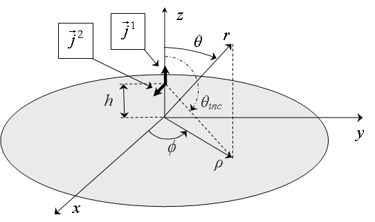
Fig. 1. The dipoles on axis of the semitransparent disk
1. Fields of the dipoles in free space
Let us consider a perpendicular magnetic dipole
and a parallel magnetic dipole
where, x, y, z are Cartesian
coordinates; ![]() and
and ![]() are the unit vectors
in direction of the Z-axis and the X-axis, respectively; δ(x) – is the Dirac delta function; mz, mx
– are moments of the magnetic dipoles.
are the unit vectors
in direction of the Z-axis and the X-axis, respectively; δ(x) – is the Dirac delta function; mz, mx
– are moments of the magnetic dipoles.
Radial ![]() , meridional
, meridional ![]() and azimuthal
and azimuthal ![]() components of magnetic field
of the magnetic dipoles in free space are
components of magnetic field
of the magnetic dipoles in free space are

in a case of the
perpendicular magnetic dipole, and

in a case of the parallel
magnetic dipole. Here, r, θ, ![]() are spherical coordinates;
are spherical coordinates; ![]() ;
; ![]() ; λ is wavelength;
; λ is wavelength; ![]() .
.
Let us consider a perpendicular electric dipole
and a parallel electric dipole
Here, pz,
px – are moments of the electric dipoles. Components of the
magnetic field of the perpendicular and parallel electric dipole in free space are
respectively

and

2. Scattering field in the Kirchhoff approximation
Let us define
the asymptotic expressions for azimuthal ![]() and meridional
and meridional ![]() components of field in far
zone of the electric and magnetic dipoles. The dipoles locate on the axis of
the disk of radius R on distance h above the disk (Fig. 1). These
expressions in the Kirchhoff approximation are
components of field in far
zone of the electric and magnetic dipoles. The dipoles locate on the axis of
the disk of radius R on distance h above the disk (Fig. 1). These
expressions in the Kirchhoff approximation are


In (9), (10) the variable ![]() for the perpendicular magnetic
dipole or the parallel electric dipole. The variable
for the perpendicular magnetic
dipole or the parallel electric dipole. The variable ![]() for the parallel magnetic dipole or the
perpendicular electric dipole. Radial
for the parallel magnetic dipole or the
perpendicular electric dipole. Radial ![]() and azimuthal
and azimuthal ![]() components of an electric current of semitransparent
disk are determined using a boundary condition
components of an electric current of semitransparent
disk are determined using a boundary condition ![]()

The radial ![]() , meridional
, meridional ![]() and azimuthal
and azimuthal ![]() component in (9)-(11) corresponds to the radial, meridional
and azimuthal component in (3), (4), (7) or (8) of analyzed dipole
component in (9)-(11) corresponds to the radial, meridional
and azimuthal component in (3), (4), (7) or (8) of analyzed dipole ![]() ,
, ![]() ,
, ![]() or
or ![]() , respectively. Components of field in far zone of rings of
radial and azimuthal electric currents of radius ρ are
, respectively. Components of field in far zone of rings of
radial and azimuthal electric currents of radius ρ are

Here ![]() is the Bessel function of order m,
is the Bessel function of order m,
![]() for the perpendicular
magnetic and electric dipoles, and
for the perpendicular
magnetic and electric dipoles, and ![]() for the parallel magnetic and electric dipoles.
for the parallel magnetic and electric dipoles.
3. The asymptotic expressions of field near the axis
We assume that
reflection and transmission coefficients are slowly varying functions. We use
the stationary phase method [26] in a case of stationary point far from the end
point to evaluate asymptotically the integrals (9), (10) near the axis. In this
case the contribution of stationary point and the end point calculate apart.
The asymptotic expressions of field near the axis are

for the azimuthal component
of field, and

for the meridional component
of field. The azimuthal ![]() and meridional
and meridional ![]() component in (13), (14) corresponds to the azimuthal
and meridional component in (3), (4), (7) or (8) of analyzed dipole
component in (13), (14) corresponds to the azimuthal
and meridional component in (3), (4), (7) or (8) of analyzed dipole ![]() ,
, ![]() ,
, ![]() or
or ![]() , respectively. Scattering fields in far zone for the angles
near the axis in the Kirchhoff approximation are
, respectively. Scattering fields in far zone for the angles
near the axis in the Kirchhoff approximation are

Let us define the
front-to-back ratio  for parallel electric and magnetic dipoles in the Kirchhoff
approximation using the asymptotic expression (13) near the Z-axis:
for parallel electric and magnetic dipoles in the Kirchhoff
approximation using the asymptotic expression (13) near the Z-axis:

for the parallel magnetic
dipole, and

for the parallel electric dipole.
4. The asymptotic expressions of field far from the axis
We use the asymptotic representation of the Bessel function in (12) when the argument is large and the stationary phase method [27] in a case of a stationary point near the end point to evaluate asymptotically the integrals (9), (10) far from the axis. The asymptotic expressions of field far from the axis are

for the azimuthal component of field, and

for the meridional component
of field. The azimuthal ![]() and meridional
and meridional ![]() component in (18), (19) corresponds to the azimuthal
and meridional component in (3), (4), (7) or (8) of analyzed dipole
component in (18), (19) corresponds to the azimuthal
and meridional component in (3), (4), (7) or (8) of analyzed dipole ![]() ,
, ![]() ,
, ![]() or
or ![]() , respectively. In (18), (19)
, respectively. In (18), (19)  is the Heaviside function. Function
  is the first term
of the asymptotic expansion of the Fresnel integral
is the first term
of the asymptotic expansion of the Fresnel integral  . The arguments of the functions
 ![]() and
and ![]() in (18), (19) are
in (18), (19) are

5. The numerical solution of an integral equation
The scattering of a dipole field by the semitransparent disk can be investigated by solving a singular integral equation of the second kind numerically. Consider boundary conditions on the surface of semitransparent disk:
Here, ![]() are tangential components of the
electric and magnetic fields on the illuminated side of the semitransparent
disk;
are tangential components of the
electric and magnetic fields on the illuminated side of the semitransparent
disk; ![]() are tangential components of the electric and magnetic
fields on the dark side of the semitransparent disk;
are tangential components of the electric and magnetic
fields on the dark side of the semitransparent disk; ![]() is the unknown electric current on the disk; and
is the unknown electric current on the disk; and ![]() is the impedance tensor with complex components. In the polar coordinates (Fig. 1) the
boundary conditions (21) take the form
is the impedance tensor with complex components. In the polar coordinates (Fig. 1) the
boundary conditions (21) take the form
The electric current on the
disk is associated with the tangential component of the electric field on the
disk's surface through the impedance tensor ![]() :
:

where  ,
,  . Consider the boundary condition
 ![]() . The tangential component of the electric field consist of
an electric field of a dipole in free space
. The tangential component of the electric field consist of
an electric field of a dipole in free space ![]() and an electric field of the
unknown electric current which expresses in terms of a Green’s tensor . Thus,
we obtain an integral equation of the second kind relative to the unknown
electric current of the disk:
and an electric field of the
unknown electric current which expresses in terms of a Green’s tensor . Thus,
we obtain an integral equation of the second kind relative to the unknown
electric current of the disk:
Here, ![]() is the Green’s tensor;
is the Green’s tensor; ![]() is the surface of
the disk. We use the method of moments and the algorithm described in [21,
22,
25] to solve the integral equation (24). The unknown electric current
is the surface of
the disk. We use the method of moments and the algorithm described in [21,
22,
25] to solve the integral equation (24). The unknown electric current ![]() shall be decomposed over basis of triangular elements:
shall be decomposed over basis of triangular elements:

Here, ![]() are unknown current amplitudes;
are unknown current amplitudes; ![]() is the radial unit vector;
is the radial unit vector; ![]() is the azimuthal unit vector. Basic
functions with bases
is the azimuthal unit vector. Basic
functions with bases ![]() and
and ![]() have the form
have the form

for the perpendicular magnetic dipole, and

for the parallel electric and magnetic dipoles. The method of moments reduces the problem of scattering to a system of linear algebraic equations. A matrix of the unknown current’s amplitudes can be determined solving this system:
Elements of matrix of own and mutual
impedances ![]() are calculated by numerical
integration of the Green's tensor components
are calculated by numerical
integration of the Green's tensor components ![]() and the basic functions:
and the basic functions:

A representation of components ![]() in spectral form was used during calculations of the own and
"nearest" mutual impedances in the matrix
in spectral form was used during calculations of the own and
"nearest" mutual impedances in the matrix ![]() . The basic function was decomposed into a two-dimensional
Fourier integral over flat sheets of electric current. Integral over the
surface S´ in (29) was determined by integrating fields of the flat
sheets with components
. The basic function was decomposed into a two-dimensional
Fourier integral over flat sheets of electric current. Integral over the
surface S´ in (29) was determined by integrating fields of the flat
sheets with components ![]() . A representation
. A representation ![]() in source-wise form for a ring of radial and azimuthal current
in the spherical coordinates was used for purpose of reducing computation time in
calculating the "distant" mutual impedances in the matrix
in source-wise form for a ring of radial and azimuthal current
in the spherical coordinates was used for purpose of reducing computation time in
calculating the "distant" mutual impedances in the matrix ![]() . Elements of a matrix
. Elements of a matrix ![]() which describes an interaction of field of a dipole and the
current of the disk have the following form:
which describes an interaction of field of a dipole and the
current of the disk have the following form:

Elements of matrix ![]() are defined as
are defined as

The scattering field is determined by summing the field of a dipole (3), (4), (7) or (8), and the field of the electric current of the disk. The field of the disk’s electrical current is determined by numerical integration of fields of radial and azimuthal electrical current’s rings. The integration was performed over radius of the rings with amplitude distribution (25).
6. The numerical and asymptotic research of scattering by the disk
Let us
consider a semitransparent disk of radius R=2λ with magnitudes and arguments of the
reflection and transmission coefficients ![]() and
and ![]() which are shown in fig. 2. The components
which are shown in fig. 2. The components ![]() of impedance tensor (23) are
shown in fig. 3. These components are normalized to W0.
of impedance tensor (23) are
shown in fig. 3. These components are normalized to W0.
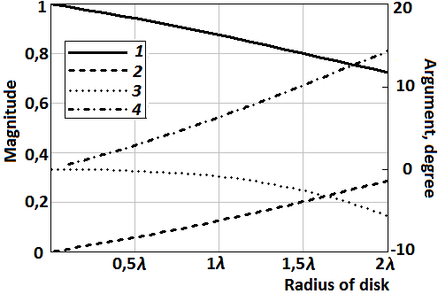
Fig. 2. The distribution of magnitudes and arguments of the reflection and transmission coefficients: 1 – magnitude of the reflection coefficient; 2 – magnitude of the transmission coefficient; 3 – argument of the reflection coefficient; 4 – argument of the transmission coefficient
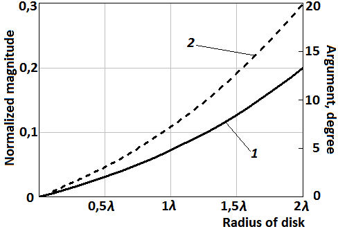
Fig. 3. The distribution of components of the impedance tensor (23) on the disk’s surface: 1 – normalized magnitude of the impedance; 2 – argument of the impedance
Numerical
results obtained using the numerical solution of the integral equation, the
numerical integration of the Kirchhoff integral (formulas (9) and (10)) and the
asymptotic formulas (13), (14), (18), (19) are shown in fig. 4 – 9. Figures 4
and 5 show patterns of the parallel magnetic dipole mounted on the disk in Е-plane  and Н-plane
![]() , respectively. Figures 6
and 7 show patterns of the parallel electric dipole located on distance h=2λ above the disk in Е-plane
, respectively. Figures 6
and 7 show patterns of the parallel electric dipole located on distance h=2λ above the disk in Е-plane ![]() and Н-plane
and Н-plane  , respectively. Figure 8
shows patterns
, respectively. Figure 8
shows patterns ![]() of
the perpendicular magnetic dipole located on distance h=1.5λ above the disk. Figure
9 shows patterns
of
the perpendicular magnetic dipole located on distance h=1.5λ above the disk. Figure
9 shows patterns ![]() of the perpendicular electric dipole mounted on the disk.
of the perpendicular electric dipole mounted on the disk.
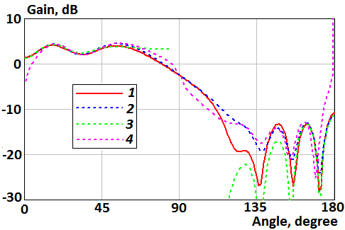
Fig. 4. Patterns of the parallel magnetic dipole mounted on the disk in Е-plane: 1 – the numerical solution of the integral equation; 2 – the numerical integration of the Kirchhoff integral (formula (9)); 3 – the asymptotic formula (13); 4 – the asymptotic formula (18).
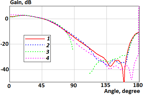
Fig. 5. Patterns of the parallel magnetic dipole mounted on the disk in H-plane: 1 – the numerical solution of the integral equation; 2 – the numerical integration of the Kirchhoff integral (formula (10)); 3 – the asymptotic formula (14); 4 – the asymptotic formula (19)
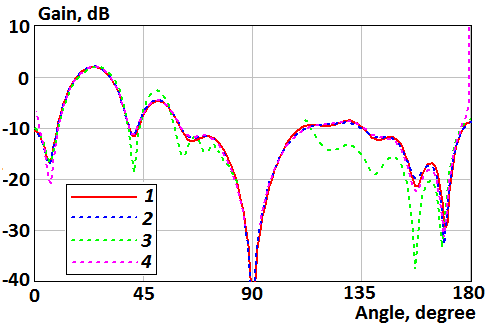
Fig. 6. Patterns of the parallel electric dipole above the disk in Е-plane: 1 – the numerical solution of the integral equation; 2 – the numerical integration of the Kirchhoff integral (formula (9)); 3 – the asymptotic formula (13); 4 – the asymptotic formula (18)
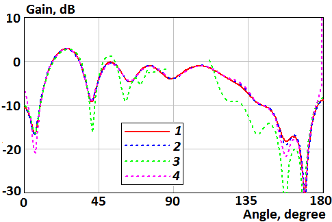
Fig. 7. Patterns of the parallel electric dipole above the disk in H-plane: 1 – the numerical solution of the integral equation; 2 – the numerical integration of the Kirchhoff integral (formula (10)); 3 – the asymptotic formula (14); 4 – the asymptotic formula (19)
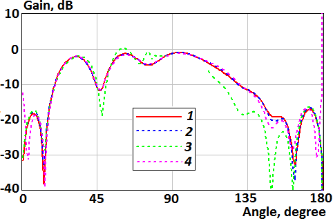
Fig. 8. Patterns of the perpendicular magnetic dipole above the disk: 1 – the numerical solution of the integral equation; 2 – the numerical integration of the Kirchhoff integral (formula (10)); 3 – the asymptotic formula (14); 4 – the asymptotic formula (19)
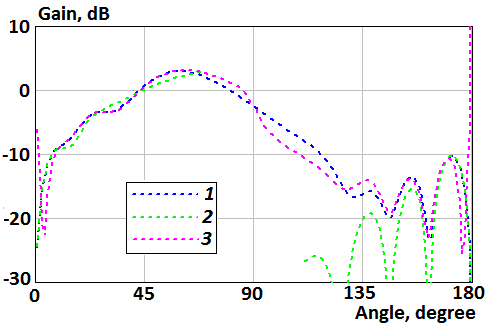
Fig. 9. Patterns of the perpendicular electric dipole mounted on the disk: 1 – the numerical integration of the Kirchhoff integral (formula (9)); 2 – the asymptotic formula (13); 3 – the asymptotic formula (18)
Figures 4-9
show that Kirchhoff approximation has good agreement with the numerical
solution of integral equation. Also, the asymptotic formulas (18), (19) are
good everywhere besides ![]() and
and ![]() , and formulas (13), (14) are
good in these regions. It make possible to calculate scattering fields in full
space using formulas (13), (14), (18), (19).
, and formulas (13), (14) are
good in these regions. It make possible to calculate scattering fields in full
space using formulas (13), (14), (18), (19).
7. Sample of optimization
Let us optimize transparency of a disk of radius R=2λ to reduce the back radiation of a parallel magnetic dipole located on distance h=0.05λ above the disk. We consider two goal parameters which are determined as a ratio of mean-square power in lower hemisphere of a disk to mean-square power in upper hemisphere in E- and H-plane. The goal parameter writes for E- and H-plane, respectively, as

and

In (32), (33) the
asymptotic representations of ![]() and
and ![]() are used and it assumes
that
are used and it assumes
that ![]() . It was assumed that the
disk is perfectly conducting in its center (i.e.
. It was assumed that the
disk is perfectly conducting in its center (i.e. ![]() and
and ![]() ). This condition allows to apply results to patch antennas with perfectly
conducting ground.
). This condition allows to apply results to patch antennas with perfectly
conducting ground.
The goal parameters
are minimized by optimization of magnitudes of reflection coefficients ![]() ,
, ![]() and transmission coefficients
and transmission coefficients ![]() ,
, ![]() using the gradient optimization method for purpose of
reducing the back radiation in lower hemisphere. The optimal distributions of magnitude
of reflection and transmission coefficients and components of tensor (23) are
shown in fig. 10, 11. We supposed the argument of these coefficients is zero. Distribution
of magnitude of reflection and transmission coefficients
using the gradient optimization method for purpose of
reducing the back radiation in lower hemisphere. The optimal distributions of magnitude
of reflection and transmission coefficients and components of tensor (23) are
shown in fig. 10, 11. We supposed the argument of these coefficients is zero. Distribution
of magnitude of reflection and transmission coefficients ![]() ,
, ![]() and
and ![]() ,
, ![]() is shown in fig. 10. Distribution of magnitude of
tensor’s component
is shown in fig. 10. Distribution of magnitude of
tensor’s component ![]() and
and ![]() is shown in fig. 11. These
magnitudes are normalized to W0.
is shown in fig. 11. These
magnitudes are normalized to W0.
Figures 12 and
13 show patterns of the parallel magnetic dipole located above the
semitransparent disk of radius R=2λ with the optimal transparency in Е-plane  and Н-plane
 ![]() , respectively. These
figures show curves of the numerical solution of the integral equation for the
semitransparent disk and perfectly conducting disk of the same radius.
, respectively. These
figures show curves of the numerical solution of the integral equation for the
semitransparent disk and perfectly conducting disk of the same radius.
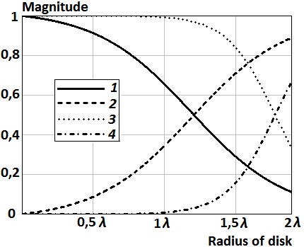
Fig.
10. The distribution
of the magnitude of reflection and transmission coefficients on the disk’s surface:
1 – magnitude of the reflection coefficient ![]() ; 2 – magnitude of the
transmission coefficient
; 2 – magnitude of the
transmission coefficient ![]() ; 3 – magnitude of the reflection coefficient
; 3 – magnitude of the reflection coefficient ![]() ; 4 – magnitude of the
transmission coefficient
; 4 – magnitude of the
transmission coefficient ![]()
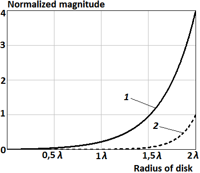
Fig.
11. The distribution
of components of the impedance tensor (23) on the disk’s surface: 1 – normalized
magnitude of ![]() ; 2 – normalized magnitude of
; 2 – normalized magnitude of ![]()
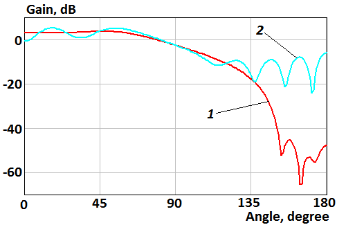
Fig. 12. Patterns of the parallel magnetic dipole located above the disk in Е-plane: 1 – the semitransparent disk; 2 – the perfectly conducting disk
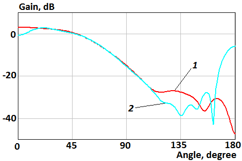
Fig. 13. Patterns of the parallel magnetic dipole located above the disk in H-plane: 1 – the semitransparent disk; 2 – the perfectly conducting disk
Figures 12, 13
show that radiation of parallel magnetic dipole in the lower hemisphere is
reduced when transparency increases from center to edge of the disk as well as argument
of coefficients of reflection and transmission and components ![]() and
and ![]() of impedance tensor (23) is zero. The front-to-back ratio of
the parallel magnetic dipole in this case is 50.9 dB and 5.2 dB for the
semitransparent and perfectly conducting disk, respectively.
of impedance tensor (23) is zero. The front-to-back ratio of
the parallel magnetic dipole in this case is 50.9 dB and 5.2 dB for the
semitransparent and perfectly conducting disk, respectively.
Conclusions
Asymptotic expressions for scattering field of an arbitrarily oriented magnetic and electric dipole located on axis of a semitransparent disk were obtained. Formulas for the front-to-back ratio for dipoles oriented parallel to the disk were presented.
Distribution of transparency for the radius of a disk 2λ was optimized which provide significant reducing of back radiation of parallel magnetic dipole above the disk.
References
1. Leitner A., Spence R. D. Effect of a Circular Ground Plane on Antenna Radiation // Journ. of Appl. Physics. Oct. 1950. V. 21. №10. pp. 1001–1006.
2. Storer J. E. The Radiation Pattern of an Antenna over a Circular Ground Screen // Journ. of Appl. Physics. May 1952. V. 23. №5. pp. 588–593.
3. Tang C. L. On the Radiation Pattern of a Base-Driven Antenna Over a Circular Conducting Screen // Journal of the Society for Industrial and Applied Mathematics. Dec. 1962. V. 10. № 4. 695–708.
4. Keller J. B. The field of an antenna near the center of a large circular disk // Journal of the Society for Industrial and Applied Mathematics. Dec. 1963. V. 11. № 4. 1110–1112.
5. Lopez A. R. The geometrical theory of diffraction applied to antenna pattern and impedance calculation // IEEE Trans. on Anten. and Prop. V. AP-14. № 1. Jan. 1966. pp. 40–45.
6. Sang-Bin Rhee Monopole Antenna with a Finite Ground Plane in the Presence of an Infinite Ground // Supplemental technical report. Nov. 1967. URL: http://www.dtic.mil/dtic/tr/fulltext/u2/a007269.pdf.
7. Hahn K.F., Fikioris J.G. Impedance and Radiation Pattern of Antennas above Flat Discs // IEEE Trans. Jan. 1973. V. AP-21. № 1. pp. 97–100.
8. Awadalla K.H., Maclean T.S.M. Monopole Antenna at Center of Circular Ground Plane: Input Impedance and Radiation Pattern // IEEE Trans. March 1979. V. AP-27. № 2. pp. 151–153.
9. Richmond J. H. Monopole antenna on circular disk // IEEE Trans. on Anten. and Prop. V. AP-32. № 12. Dec. 1984. pp. 1282–1287.
10. Weiner M. M., Cruze S. P., Li Cho-Chou and Wilson W. J. Monopole elements on circular ground planes. Northwood, MA: Artech House. 1987.
11. Ibrahim H. M., Stephenson D. T. Radiation patterns of a λ/4 monopole mounted on thick finite square and circular ground planes // International Journal of Electronics. 1988. V. 64. № 3. pp. 345–358.
12. Ibrahim H. M. Radiation patterns of a λ/4 monopole mounted on a small thick circular disc // International Journal of Electronics. 1990. V. 68. № 2. pp. 283–292.
13. Weiner M. M. Monopole antennas. New York, NY: Marcel Dekker. 2003.
14. Zivkovic Z., Senic D., Bodendorf C., Skrzypczynski J., Sarolic A. Radiation pattern and impedance of a quarter wavelength monopole antenna above a finite ground plane // In proc. of 20-th International Conference on Software, Telecommunications and Computer Networks (SoftCOM). 2012.
15. Lusekelo Kibona Impact of finite circular ground plane on the radiation patterns of the monopole antenna // International Journal of Software & Hardware Research in Engineering. Dec. 2013. V. 1. № 4. pp. 10–16. URL: http://ijshre.com/wp-content/uploads/2013/12/IJSHRE_1412.pdf.
16. Kishk A.A., Shafai L. The Effect of Various Parameters of Circular Microstrip Antennas on Their Radiation Efficiency and the Mode Excitation // IEEE Trans. August 1986. V. AP-34. № 8. pp. 969–976.
17. Bhattacharyya A.K. Effects of Finite Ground Plane on the Radiation Characteristics of a Circular Patch Antenna // IEEE Trans. February 1990. V. AP-38. № 2. pp. 152–159.
18. Noghanian S., Shafai L. Control of microstrip antenna radiation characteristics by ground plane size and shape // IEE Proceedings Microwaves, Antennas and Propagation. June 1998. V. 145. № 3. pp. 207–212.
19. Lolit Kumar Singh L., Bhaskar Gupta, Partha P. Sarkar Effects of Different Shaped and Size Ground Planes for Different Shaped Patch Antennas Characteristics // International Journal on Recent Trends in Engineering & Technology. Nov. 2010. V. 4. № 3. pp. 17–21.
20. Saeed I. Latif, Shafai L. Pattern Equalization of Circular Patch Antennas Using Different Substrate Permittivities and Ground Plane Sizes // IEEE Trans. Oct. 2011. V. AP-59. № 10. pp. 3502–3511.
21. Клионовски К. К. Характеристики направленности проводящих экранов круглой формы // Антенны. 2011. № 12. С. 31–37.
22. Kaloshin V. A., Klionovski K. K. Scattering of dipole field by perfectly conducting disk // Journal of radio electronics. 2013. №.12. URL: http://jre.cplire.ru/jre/dec13/7/text.pdf.
23. Ufimtsev P. Ya. Diffraction of electromagnetic waves at black bodies and semitransparent plates // Radiophysics and Quantum Electronics. 1968. V. 11. № 6. pp. 527–538.
24. Wang R.W., Liepa V.V. Reduction of the edge diffraction of a circular ground plane by using resistive edge loading // Anten. and Propag. Soc. Int. Symp. June 1985. V. 23. pp. 769–771.
25. Klionovski K. K. Theoretical and Experimental Research of Diffraction on Round Semitransparent Ground Plane // IEEE Trans. on Anten. and Propag. 2013. vol. 61. № 6. pp. 3207–3215.
26. Felsen L., Marcuvitz N. Radiation and scattering of waves. Hoboken, New Jersey, USA: John Wiley & Sons. 2003.
27. Lewis R. M. Asymptotic theory of transients // in book «Electromagnetic Wave Theory», Part 2 (ed. J. Brown), New York, USA: Pergamon Press. 1967. p. 864.