c1.gif (954 bytes) "JOURNAL OF RADIOELECTRONICS" N 10, 2003

contents

discussion

c2.gif (954 bytes)


A Noise Reduction Algorithm Suitable for Hardware Implementation


Vladimir Radenkovic1, Miodrag Temerinac2, Nikola Teslic1, MiroslavPopovic1


1 - University of Novi Sad, Faculty of Engeenering, Fruskogorska 11a, 21000 Novi Sad, Serbia & Montenegro, e-mail: vradenkovic@tvns.co.yu

2 – Micronas GmbH, Hans Bunte Str. 9, Freiburg, Germany


Received  October 29, 2003  


        In recent years there have been a lot of research and development activities, in both industry and academia, in area of image processing and in noise reduction in particular. However, there is a need for more research efforts in this area because most of the proposed algorithms are to complex for the implementation on embedded platforms, which typically have very limited resources. This paper should be viewed as a contribution to these efforts. In the paper we propose new algorithm and its hardware implementation for the impulse noise reduction filter for the satellite TV picture. This space 2D filter processes the picture in real-time. Its structure is based on median filter and it operates by replacing the noise damaged pixels with values calculated by median filter 3x3. To determine whether a pixel is a noise damaged or not, morphological functions are applied, and because of this the filter was named NMF (New Morphological Filter). The filter equally well reduces the real impulse noise present in a satellite TV picture, in real-time, as it does the salt and paper type of impulse noise. The algorithm hardware implementation was done in FPGA (Field Programming Gate Array) integrated circuit. The NMF’s quality is low mathematical complexity, small demand for hardware resources, a large signal to noise ratio, as well as fine preservation of both edges and tiny details in the filtered picture.


Keywords: Morphological filter, Noise reduction, Satellite TV, Hardware implementation, FPGA, Salt and paper, Image processing, Mathematical complexity


  1. INTRODUCTION

  2. Concept of the NMF Filter

  3. short description of algorithms used as references

  4. results

  5. Hardware implementation

  6. TEST ENVIRONMENT

  7. Conclusions

  8. Literature


1. INTRODUCTION


One of the most interesting peculiarities of real-time picture processing is the fact that the noise reduction filter quality is not measured only by the filtration success in terms of the filtered picture quality, but also by the demand for hardware resources necessary for its implementation. The demand for the hardware resources could be characterized by the size of the integrated circuit (e.g. number of gates needed, capacity of the memory, etc.), and its working frequency, i.e. clock rate.

If the proposed filter is to be used in commercial SAT TV sets, this means the production cost of such a filter should be relatively low. The production cost is in relation to the number of logical circuits needed for implementation of the algorithm. For this reason it is necessary that the algorithm should be as simple as possible, i.e. its complexity should be as low as possible.

Operational speed is an essential characteristic. It depends on the mathematical complexity of the algorithm. Additionally, the operational speed of the integrated circuit could be reduced by the decomposition of the algorithm into a set of hardware blocks which operate in parallel. On the other hand, if the algorithm could not be decomposed in such a way, this would lead to a structure with a series of hardware blocks, where each of the blocks must wait for a result (output) of the previous block (its input) in order to perform the processing, and to finally produce its own result. It is clear that serial connection of hardware blocks increases the overall delay and thus implies higher operation speed, i.e. working frequency.

Exploiting of memory resources is another significant characteristic, so for these reasons the proposed filter is designed as a space two dimensions (2D) filter, which processes each half-picture in order to avoid additional memories for storing half-pictures.

Our goal was to implement a filter algorithm in the FPGA ALTERA 10K 100, i.e. the algorithm that respects the actual limits of hardware resources available in this FPGA [1]. The problem in finding such an algorithm is that the unique criterion for the filter quality estimation does not exist in the literature. One of the commonly accepted objective criterions is SNR. Other criterions are subjective, and they address the preservation of edges, contours, and fine details, the corresponding marks are “good” and “bad”. J.Pitas and A.Venestanopoulus [2] propose the following five criterions for the filter quality estimation:

  1. preservation of fine details,
  2. preservation of edges,
  3. bias,
  4. SNR, and
  5. mathematical complexity


Pitas and Venetsanopoulos [2] have compared the nonlinear image processing algorithms known from the literature. The result of this comparison for the algorithms that are most relevant to the problem at hand is given in the Table 1.


Table 1: The result of the comparison of the relevant algorithms from the literature

Filter

Comparison Criterions

A

B

C

D

E

Median

0

2

2

2

1

Separate Median

0

2

2

2

2

Recursive

Median

0

2

2

2

1

Dilation

0

2

0

0

2

Erosion

0

2

0

0

2

Open

0

2

2

0

1

Close

0

2

2

0

1

C/O

0

2

2

1

0

O/C

0

2

2

1

0


The comparison criterions in the Table 1 are as follows:

A: preservation of fine details

B: preservation of edges

C: bias

D: salt and paper noise reduction efficiency

E: mathematical complexity


The marks for the criterions in Table 1 are defined in the Table 2:


Table 2: The definition of marks for the criterions given in Table 1.

A, B, D

0: bad

1: average

2: good

C

0: strong

1: average

2: weak

E

0: large

1: average

2: small


Table 2 shows that bad preservation of fine details is the greatest disadvantage of median-based filters including Median [2],[3],[4],[5],[6],[7],[8],[9],[10], Separate Median [11], and Recursive Median [12]. On the other hand, increased noise reduction efficiency and decreasing of bias by the Morphological filters [13],[14],[15],[16] is paid with the increased mathematical complexity, yielding higher demand for hardware resources.

The NMF filter proposed in this paper was designed by combining the principles of morphological and median filters in order to achieve high level of noise reduction, measured by SNR, and at the same time good preservation of fine details by using median approximation of neighboring pixels. In essence, the NMF filter algorithm is based on the application of mathematical morphology [17].

For the evaluation of the quality of the proposed filter, in terms of noise reduction, we use the signal/noise ratio (SNR), which is the usual objective measure in such a case.

In the paper we compare the NMF with three similar filters known from the literature [18-20]. Filters will be compared according to their mathematical complexity measured by the number of needed operations, efficiency of the noise reduction measured by the SNR, and the quality of preservation of edges and fine details in the picture measured by subjective impression of differences between the pictures produced by various algorithms and the original picture with presence of noise.

The special advantage of the proposed NMF algorithm, in comparison with the three algorithms from the literature [18-20], is that it is more successful in noise reduction of the real noise present in the real satellite TV picture. The real noise signal manifests in a form of bright and dark dashes a few pixels long in contrast to the theoretical paper and salt noise that affects only individual pixels.

Filter efficiency was evaluated subjectively since in realty there is no original noiseless sequence. The results have been confirmed by a theoretic salt-and-pepper type noise model upon which measuring of the signal/noise ratio have been carried out.


2. Concept of the NMF Filter


The requirements that impose themselves in the construction of this filter should reconcile two opposite points of view; on the one side maximal efficiency in noise reduction, and on the other side minimum edge and fine details degradation on the other. The problem faced in this complex optimization task is that both noise and fine details happen to be high-frequency components of a satellite TV signal, so by suppressing the noise, fine details are being suppressed, as well. The solution lies in construction of a filter that will filter only the spots in the picture that noise damaged.

If there is a possibility to detect impulse noise damaged picture parts, they could be selectively filtered. This means that only those pixels which are damaged by the noise get replaced by new values calculated by a median filter. The essence of the proposed concept is in an adequate detection of noise damaged picture parts.

Selective filtering of only damaged elements of a picture results in the restored picture that will have a lot more of preserved details. The improvements result in increase of the signal/noise ratio and in meeting of the subjective criteria.

The Figure 1 presents the flow chart of the filtering process. Filtered picture Fout(x,y) is obtained from the input noise damaged picture Fin(x,y) and the picture Med(x,y) that is obtained by filtering the picture Fin(x,y) through a median filter. Pixels in the output picture Fout(x,y) represent a linear combination of the noise damaged picture and the same picture filtered by a median filter.


Figure 1. Flow chart of the filtering process.


The values of the functions Med(x,y), Fin(x,y), and Fout(x,y) represent of brightness in a point (x, y). The function M(x,y), that is called the “noise map”, serves to detect the noise damaged pixels. Its value is 1 in places where pixels are damaged, and 0 in all other cases.


The filtering procedure is represented by a functional block diagram shown in Figure 2 and consists of 2 steps.


I STEP


In the first step, the function F1(x,y) is being calculated. It determines the
possible candidates for noise-damaged pixels. Each pixel for witch the luminance component value, Fin(x,y), is different from the median filtered luminance component value, Med(Fin(x,y)), is a possible candidate. The absolute value of this difference is defined as follows:

                                                            (1)

where ABS is the represents the absolute value. The absolute value is introduced of the difference is introduced so that the function F1(x,y) has non negative values.


II STEP


In second step we calculate the values of the function F2(x,y). The function F2(x,y) is used to specify the criterion for defining the candidates that could be declared as noise-damaged pixels. Pixels damaged by the noise have very high luminance component values, maximum value or values close to maximum. If we define window of size m by n pixels, e.g. 3x3, on top of the picture, the pixels with the luminance component values close to maximum, or maximum, represent the pixels damaged by the noise. The filtering process proceeds from the top to the bottom of the picture by sliding the observed window by one pixel in each step. If we define the observed pixel as a pixel in the center of the observed window, (xc,yc), the value of the difference between the F1(x,y) function maximum for the window, MAX(F1(x,y)) and F1(x,y) function value for the observed pixel, F1(xc,yc), has to be smaller than the difference between F1(xc,yc) and the F1(x,y) function minimum for the window, MIN(F1(x,y)):

                                           (2)

After simple transformation we obtain the following condition:

                                                    (3)

MAX(F1(x,y)) and MIN(F1(x,y)) represent the extrems in the observed window. By experiments we have find out that the following relaxed condition may be used in the NMF heuristic filtration algorithm:

                                                                               (4)

Let functions MAX(F1(x,y)) and MIN(F1(x,y)) be morphological functions Dilation and Erosion [17], DIL(F1(x,y)) and ER(F1(x,y)). Than condition (4) becomes the following:

                                                                     (5)

Next, in the process of filtration the noise map M(x,y) is defined as:

                                                                                             (6)

The output picture Fout(x,y)  is defined as follows:

                                                                        (7)


Figure 2. Filter NMF Block Scheme


3. short description of algorithms used as references


The most appropriate filters that have been described in the literature, which function in a similar way as the NMF are used for the comparison with the NMF. The following filters have been selected:


  1. Mitra-Kundu (MK) [18]
  2. SIGNAL ADAPTIVE MEDIAN (SAM) [19]
  3. RANK ORDERED MEAN (ROM) [20]


MK algorithm [18] observes the difference between the Med(Fin(xc,yc)) and Fin(xc,yc), and if this difference is between the two thresholds, T1 and T2, it is assumed that the pixel has not been damaged by the noise. The thresholds T1 and T2 are defined as follows:

                                                                                              (8)

                                                                                             (9)

Sl and Sh are Fin(x,y) function minimum and maximum for the observed window, respectively, while Smin and Smax are the lowest and the highest possible values of function Fin(x,y), i.e. 0 and 255.


SAM algorithm [19] differs from MK [18] in the definition of thresholds. Thresholds, T1 nad T2, are defined as follows:


                                                                                                  (10)

                                                                                                 (11)


where c=1/2, 2/3, 3/4…. , Smax=255, Smin=0, and m=Med(Fin(xc,yc))


ROM algorithm [20] sorts values of Fin(x,y) for the pixel in the observed window (e.g. 3x3) by the increasing order. The pixel in the center of the window is skipped. Let rk(n) represent the k-th element of sorted array of pixels in n-th position of the observed window. Next, the value m(n) is defined as follows:

                                                                                            (12)

Let x(n) represent the central point of the observed window in it’s n-th position in the current picture. Than the distances dk of individual elements, of sorted array of pixels, from this central point, x(n), are defined as follows:

                                                                    (13)

If the distance dk is greater than Tm, dk>Tm, the corresponding pixel is damaged, and it’s brightness value is replaced by the value m(n). The values of Tm are defined as follows:


T1=8, T2=20, T3=40, and T4=50.


In the following sections of the paper we present the results of the comparison of NMF algorithm with the three algorithms from the literature [18-20].


4. results


Mathematical complexity


The total number of mathematical operations that is used by the filtering algorithm determines its mathematical complexity [2]. The mathematical operations are divided into the following groups:


A= Series Sorting

B= Adding and deducting

C= Dividing and mulitiplying

D= Comparing

E= Logical I

F= If-else

G= Absolute value


The comparative results are presented in Table 3. It is obvious that the NMF is superior to the three algorithms from the literature since it requires only 8 operations. The most close to it is SAM, with 9 operations, MK requires a little bite more, 11 operations, and the worst one is ROM with its 27 operations.


Table 3: Mathematical complexity of the observed filters


A

B

C

D

E

F

G

TOTAL

MK

3

2

2

2

1

1

0

11

SAM

1

2

2

2

1

1

0

9

ROM

1

9

1

12

0

4

0

27

NMF

2

2

1

1

0

1

1

8


Noise reduction


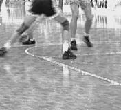
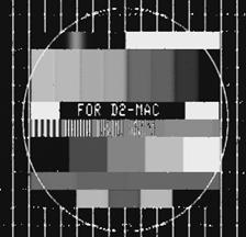
Since we had only a sequence of pictures received from the satellite TV receiver at our disposal, i.e. the original sequence of pictures sent from the TV studio was unavailable; the SNR could not be calculated. In such situation the filtering results could be evaluated only subjectively regarding the success of the real noise reduction. In our experiments we used a zoomed detail, see Fig. 4, from the TV satellite picture shown in Fig. 3.


Figure 3. Picture taken from a TV set

Figure 4. A zoomed detail from Fig. 1


Figures form 5 to 8 show filtering results for the three filters from the literature and the NMF filter proposed in this paper. It is evident that the picture in the Fig. 8, produced by the NMF filter, has the best quality from the user point of view. The quality of the picture filtered by the ROM filter is close to the quality of picture filtered by the NMF filter. The quality of the picture filtered by the MK filter seems to be lower, while the quality of the picture filtered by the SAM filter is the worst one.


Figure 5. MK Filter

Figure 6. SAM Filter

Figure 7. ROM Filter

Figure 8. NMF Filter


Next, the efficiency of the noise reduction was checked by the artificially generated noise of salt-and-pepper type noise, applied to test sequence called Car and Penndel. The picture size is 720x576.


The first pictures from the original test sequences Car and Penndel are shown in figures Fig.9 and Fig. 10, respectively.


Figure 9. Car

Figure 10. Penndel


            The test results are presented in Table 4. The Table shows the average values of SNR for the three filters from the literature, and for the NMF filter, for two values of salt and paper noise, 5% and 10%, artificially added to both of the test sequences of pictures. It is evident that the NMF is superior to other filters in all of the cases. It has been most successive for the case of 5% of salt and paper noise applied to Penndel test sequence, with the average value of SNR of 43.49 dB. The SNR [21] measure was calculated by expression (14):

         ,                                           (14)

where is N total number of pixels and xior  and xiout  are brightness values of the i-th pixel in the input and output pictures, respectively.


Table 4: SNR values for the compared filters.


5% Noise

10% Noise

FILTER

Car

Penndel

Car

Penndel

MK

28.43

35.34

26.80

30.89

SAM

30.44

40.39

29.26

36.87

ROM

27.49

38.75

26.50

35.34

NMF

34.67

43.49

32.31

39.83


Fine details preservation


Fine details evaluation was done on the test sequence Basket, which was artificially damaged by 10% of salt and paper noise. The first picture of the original test sequence is shown in Fig.11. The results produced by the three filters from the literature, and for the NMF filter, are shown on Figures from 12 to 15. The floor of basketball court is a typical detail that we used for the assessment of fine details preservation quality. If the preservation of a white line drawn on the floor is used as a criterion of the quality of preservation of fine details, it is obvious that the result of the NMF filter is the best one, while the result of the ROM filter is the worst one.

Figure 11. Basket


Figure 12. MK Filter

Figure 13. SAM Filter

Figure 14. ROM Filter

Figure 15. NMF Filter


Edges Preservation


Edges preservation evaluation was done on the Test picture, which was artificially damaged by 10% of salt and paper noise. The Test picture is shown in Fig.16. The results produced by the three filters from the literature, and for the NMF filter, are shown on Figures from 17 to 20. By observing the horizontal and vertical lines, as well as the circle it is evident that the NMF is superior to the three filters from the literature. The SAM filter seems to produce the worst result from all of the compared filters.

Figure 16. Test 


Figure 17. MK Filter

Figure 18. SAM Filter

Figure 19. ROM Filter

Figure 20. NMF Filter


5. Hardware implementation


The algorithm has been implemented in the FPGA ALTERA 10K100 which has the following limitations:

  1. The complexity of the implementation must be less than 100.000 logical circuits.
  2. The filter should be realized with 4 memories with the capacity of 1 picture line, i.e. 720 bytes, each.


The hardware implementation of the NMF filter is presented by the block scheme shown in Figure 21.


Figure 21. Electrical Schematics of the NMF Filter Hardware Implementation.


The source of the luminous component of the incoming picture is connected to the input of two linear memories with capacity of 720x1 bytes. The memory delay is 3 clock periods, i.e. z-3. In order to achieve the same horizontal position of a signal with the 3 successive lines at the input of the next block, delays of z-6 and z-3 are introduced. The structure of registers is determined by the median filter form, and in this case, it is designed for a space median of size 3x3. The median filter Median 9 introduces z-10 delay.

One of the two remaining delay lines (line memories) is used to store the already processed line of F1 function, and the other one, together with the current output from the median filter, which processes two more lines of the F1 function that are the inputs of the delay block. The delay block introduces a z-3 delay, and it is realized by calculating the 3 maximum values for each of the lines after that the total maximum has been calculated.

Based on the delays of individual elements of the filter structure, additional values of the needed signal delay are introduced, as shown in the Figure 19. Noise damaged pixels that need to be replaced are obtained at the output of the linear memory, which contains the median filtering values.

Low contour threshold determines the minimum value of F1 function that is believed to belong to the noise. It was determined experimentally that for a picture of 256 levels its value is 30.

The hardware design was done by the program package ALTERA MAX+ II version 8.3 [21]. The code was written in VHDL language [22], [23], [24] which is commonly nowadays used for the hardware designs in FPGAs. The NMF filter proposed in this paper uses 41% of ALTERA EPF10K100ARC240-2 logical circuits, and 93% of its memory, as shown in Table 5.


Table 5: Utilization of the ALTERA Integrated Circuit by the NMF Filter

Input

Pins

Output

Pins

Bidi

Pins

Memory

Bits

Memory

Utilized

LCs

LCs

Utilized

51

64

2

23040

93 %

2050

41 %


6. TEST ENVIRONMENT


The testing of the hardware implementation was carried out on IMAS development system, which has been designed by the Micronas GmbH, Freiburg. The development system consists of 3 parts and its block diagram is shown in Figure 22.


Figure 22. IMAS Development System Block Diagram.

The principal parts of the development system are the following:

  1. Board with VPC 3215C integrated circuit [25],
  2. Board with ALTERA FLEX 10K100ARC240-2 integrated circuit, and
  3. Board with DDP 3310B integrated circuit [26].


These boards are connected together to form a development system. The development system consist of the picture receiver, A/D converter, ALTERA10K100 for picture processing in digital domain, and D/A converter, which is connected to the TV receiver. Each of these integrated circuits may be accessed via a serial I2C interface in order to adjust the board parameters.

The main components on the first board are the integrated circuit VPC 3215C and two input buffers for I2C interface. There are connectors for 5 TV signals, 4 of which are used for the composite video signal and one for S-VHS. It is possible to receive signals in PAL, NTSC or SECAM standards, all of their sub-standards are included. This board’s main task is to receive the video signal and to convert it into the digital domain. More precisely, the integrated circuit VPC 3215C converts the analog video signal into the digital video signal in the form YCrCb. VPC 3215C is an integrated circuit from the VPC video processors family. In essence, the VPC 3215C it is an eight-byte video picture converter.

The second board’s main component is a programmable integrated circuit ALTERA FLEX 10K100ARC2490-2. It can be programmed via Byte Blaster cable connected to a PC computer parallel port. The noise reduction algorithm is implemented in this integrated circuit. Besides the ALTERA integrated circuit, there are two FIFO memories, with the capacity of 245.760 12-byte words, which is sufficient to receive the whole half-picture. In addition to the standard FIFO access, a random access to the selected memory block (a single block contains 40 words) is also possible, but after having it reset.

The board DDP 3310B is, in fact, a D/A converter that converts a picture from digital domain back to analog domain. It contains three 10 bytes D/A converters that receive a digital YCrCb picture, in either 4:2:2 or 4:1:1 form, and converts it into the standard RGB analog form. This picture may be than displayed on the monitor. The standard picture size is 4:3 or 16: 9, and the refreshing rate is 100 or 120 Hz. Besides it is converting the picture into the analog form, this integrated circuit, also, generates control signals for FIFO memories, for read and write operations. All of the processing in digital domain is clocked with either 27 or 32 MHz.


7. Conclusions


In this paper we have proposed the new morphological filter (NMF) algorithm for noise reduction in satellite TV picture, we have compared the NMF with the three algorithms from the literature, namely MK, SAM, and ROM, and we have presented the hardware implementation of the NMF in field programmable gate arrays (FPGA) manufactured by Altera company. The proposed NMF, space two dimensions filter, processes the picture in real-time. Its structure is based on median filter and it operates by replacing the noise damaged pixels with values calculated by median filter 3x3. To determine whether a pixel is damaged with noise or not, morphological functions are applied. In the paper we have compared the proposed NMF algorithm with the three above mentioned algorithms from the literature (MK, SAM, and ROM), from the point of mathematical complexity, SNR, fine details preservation, and edge preservation, and we have shown that the NMF is superior to MK, SAM, and ROM, in all of the respects. The filter equally well reduces the real impulse noise present in a satellite TV picture, in real-time, as it does the salt and paper type of impulse noise. The main NMF’s characteristics are low mathematical complexity, and hence small demand for hardware resources, e.g. only 41% of logical circuits in the selected Altera FPGA, a large signal to noise ratio, for both theoretical and real noise sources, as well as fine preservation of both edges and tiny details in the filtered picture.


8. Literature


[1] Data Sheet, Altera FLEX 10K Embended Programmable Logic Family Altera Corporation San Hose California USA May 1998.

[2] J. Pitas, A. Venetsanopoulos Order Statistics in Digital Image Processing, Proceedings of the IEEE, vol. 80. No. 12. Dec. 1992.

[3] J.Pitas, A.Venetsanopoulos, Adaptive filters based on order statistics, IEEE Trans. Signal Process., vol. 39, pp.518-522, Feb. 1991.

[4] M.Juhola, J.Katajainen, T.Raita, Comparison of algorithms for standard median filtering, IEEE Trans. Signal Process., vol. 39, pp. 204-208, Jan. 1991.

[5] D.S.Richards, VLSI median filters, IEEE Trans. Acoust.  Speech Signal Process. Vol. 38, pp. 145-153, Jan. 1990.

[6] S.Ranka, S.Sahni, Efficient serial and parallel algorithm for median filtering, IEEE Trans. Signal Process., vol 39, pp 1462-1466, June 1991.

[7] D.Eberly, H.Longbotham, J.Aragon, Complete classifisation of roots to one-dimensional median and rank-order filters, IEEE Trans. Signal. Process., vol.39, pp. 197-200, Jan. 1991.

[8] Z. Wang, D. Zhang, Progressive Switching Median Filter for the Removal of Impulse Noise from Highly Corrupted Images, IEEE Trans. on Circuits and Systems-II: Analog and Digital Signal Process., vol. 46, no. 1., Jan. 1999.

[9] H. Hwang, R. A. Haddad, Adaptive Median Filters: New Algorithms and Results IEEE Trans. on Image Process., vol 4, no. 4, April 1995.

[10] C. J. Juan, Modified 2D Median Filter for Impulse Noise Suppression in a Real-Time System, IEEE Transactions on Consumer Electronics, vol. 41, no. 1, Feb. 1995.

[11] P. M. Narendra, A separabile median filter for image noise smoothing, IEEE Trans. Pattern Anal. Machine Intell., vol. 3, pp. 20-29, Jan. 1981.

[12] G. Arce, N. C. Gallagher, Stohastic analysis for the recursive median filter process. IEEE Trans. Inform. Theory, vol. 34, pp. 669-679, July 1988.

[13] P. Maragos, R. Schafer, Morphological Filters-Part I : Their Set-Theoretic Analysis and Relations to Linear Shift-Invariant Filters, IEEE Transactions ASSP vol. 35. no. 8, pp. 1153-1169, August 1987.

[14] P. Maragos, R. Schafer, Morphological Filters-Part II : Their Relations to Median, Order-Statistic, and Stack Filters, IEEE Transactions ASSP vol. 35. no. 8, pp. 1170-1184, August 1987.

[15] P. Maragos, A Representation Theory for Morphological Image and Signal Processing, IEEE Transactions PAMI, vol. 11. no. 6, pp. 586-599, June  1989.

[16] J.Gil, M. Werman, Computing 2-D Min, and Max Filters, IEEE Transactions PAMI, vol. 15. no. 5, pp. 504-507, May 1993.

[17] R. Jones, I. Svalbe, Algorithms for the Decomposition of Gray-Scale Morphological Operations, IEEE Transactions PAMI vol. 16. no. 6, pp. 581-588, June 1994.

[18] A.Kundu, S.K.Mitra, P.P.Vaidyanathan,  Application of Two-Dimensional Generalized Man Filtering for Removal of Impulse Noise from Images, IEEE            Transactions on Acoustic, Speech, Signal Processing, vol.32,pp. 600-609, June 1984.

[19] R.Berstein,  Adaptive Nonlinear Filters for Simultaeous Removal of Different  Kinds of Noise in Images,IEEE Transactions on Circuits and Systems, pp. 1275-1291, nov. 1987.

[20] E. Abreu, M. Lightstone, S. Mitra, K. Arakawa, A New Efficient Approach for the Removal of Impulse Noise from Highly Corrupted Images, IEEE Trans. on image    processing, vol. 5., no. 6, June 1996.

[21] O. Egger, W. Li, M. Kunt, High Compression Image Coding Using an Adaptive    Morphological Subband Decomposition, Proceedings of the IEEE, vol. 83. no. 2, Feb. 1995.

[22] Altera MAX + plus II VHDL ver. 8.3, Altera Corporation, San Jose California    USA, December 1996.

[23] Altera MAX + plus II Getting Started, Altera Corporation, San Jose California USA, September 1997.

[24] K. Skahill, VHDL for programmable logic, Addison-Wesley Publishing Company inc., Mentlo Park California USA, 1996.

[25] Preliminary Data Sheet VPC 3205C, VPC 3215 C Video Processor Family Micronas Freiburg Germany, August 1997.

[26] Preliminary Data Sheet DDP 3310B Display and Deflection Processor Micronas Freiburg Germany, May 1998.


c3.gif (955 bytes)

contents

discussion

c4.gif (956 bytes)