Demonstration Of Chromatic Dispersion Compensation Fibre Using Circular Hole PCF with Different Pitch and Diameters
Manan Trivedi, Ravi Godara
Suresh Gyan Vihar University, India
The paper is received July 23, 2013
Abstract. In recent years PCFs made of silica and air hole has provided a new approach for dispersion compensation. For dispersion compensating fibers , large negative dispersion D (ps/km-nm) is required. To maintain the flat and zero dispersion in photonic crystal fiber (PCF) different air hole diameter and different pitches has been introduced. These differences in diameter and pitches gives different dispersion graphs and after comparison we get that design which has lowest dispersion among them. This paper proposes a new geometry of PCFs which uses ‘Circular’ holes instead of square or elliptical holes which gives large negative dispersion without high doping .
Keywords: circular hole PCF; dispersion compensation; negative dispersion.
I. INTRODUCTION
Conventional single mode fibre (CSFs) based on weakly guiding structures of doped silica can be tailored to exhibit a variety of desirable modal characteristics in terms of loss/gain, dispersion, field confinement. Due to the small index variation over the transverse cross section, modal characteristics of conventional dispersion compensating fibers (DCFs) cannot be changed significantly to realize effective dispersion compensation. This shortcoming may be overcome for the design of PCFs whose transverse cross sections consist of a central high index defect (or missing a hole) in a regular triangular (or hexagonal) array of air holes . There are only two designs parameters, namely the air hole diameter d, the pitch L. PCF can be tailored to exhibits unique and useful characteristics due to a strong function of wavelength of the cladding. In order to design a practical DCF based on PCF, such an over-simplified model may not be sufficient as it deviates significantly from the real index profile. Further, in order to optimize the dispersion, it is necessary to investigate in a systematic fashion dispersion properties of PCF with different combination of PCF parameters by a rigorous vector solver. It is, therefore, of practical interest to improve the existing design so as to explore the potential of PCF for dispersion compensation.
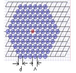
Fig.1. The cross section of PCF with a regular triangular air-hole array defined by air hole diameter d and the pitch L.
II. THEORY
The group velocity dispersion or simply dispersion D(l) of PCF can be directly calculated from the modal effective index heff(l) of the fundamental mode over a range of wavelength :
D(l) = - l d2 heff(l)/c dl2 (1)
where c is the velocity of light in a vaccum and l is the operating wavelength. In order to design required dispersion and utilize the scaling effect of the PCF size on dispersion , the total dispersion D(l) is calculated as a sum of the geometrical dispersion Dg(l) and the material dispersion Dm(l) in the first order approximation:
D(l) » Dg(l) + G(l) * Dm(l) (2)
Where G(l) is the confinement factor in silica. In most cases G(l) » 1, as almost all energy concentrates in silica with high refractive index for PCFs, or the core has similar material properties with the cladding for CSFs. Dg(l) can be obtained without considering the material dispersion ( e.g. the refractive index of silica hsilica = 1.45) and Dm(l) can be obtained directly from the general three-term Sellmeier formula. The reason for removing Dm(l) from D(l) is that Dm(l) is mostly determined by the wavelength dependence of the fibre material (e.g., the pure silica) and, therefore, cannot be altered very much in design for engineering of D(l). On the other hand, Dg(l) of PCF is strongly related to the structure and therefore con be changed significantly to achieve desired characteristics of D(l). Through properly scaling Dg(l), the optimized PCF structure for some
desired dispersion at some specific wavelengths might be easily obtained with considering Dm(l).
III. DISPERSION COMPENSATION DESIGNS
Dispersion compensation photonic crystal fibre has been designed with refractive index 1.45 with triangular lattice with Circular holes and in center air hole omitted that means creating a high inde defect at centre working as core, the modes of interest are guided only along the fibre axis.
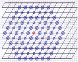
Fig.2. Circular hole PCF with alternate layer air-hole diameter change.
There are total no. of rings are 5.d1 is diameter of large ring and d2 is diameter of small ring. In fig 2 (a) three designs are made which have constant pitch i.e.
L= 1.6, d1=0.60, d2=0.3(first design), d1=0.70, d2=0. 4 (second design), d1=0.8, d2=0.50(third design).
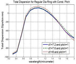
After comparing the graphs of these designs, large negative dispersion at 1.55mm is -178 (ps/km-nm) from first design (regular dark line). In fig 3 (b) all the rings have same diameter in each design with constant pitch L= 1.0. d1=0.72 (first design),d1= 0.76 (second design), d1=0.80 (third design).After comparing we get -202 (ps/km-nm) at 1.55 mm for first design (regular dark line) which is lowest dispersion among all these three graphs.
(a)
(b)
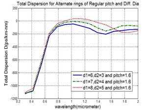
Fig.3. (a) Dispersion as a function of wavelength for alternate layer hole diameter change. (b) Possible PCF structure with regular diameter. (Pitch L constant 1.6)
In fig 4 (a) diameter is constant with alternate ring hole diameter change for all three designs i.e. d1=0.80, d2=0.50 but pitch is different i.e. 1.4, 1.6, 1.8 for first, second, third design respectively. After comparing dispersion graphs as a function of wavelength for these designs we get -164 (ps/km-nm) dispersion at 1.55 mm for first design (regular dark line) which is lowest among all these three designs. In fig 4 (b) all the rings have same diameter which is constant & it is d1=0.80 but different pitches which are 1.4,1.6,1.8 respectively. After plotting dispersion graphs, we compare these graphs with each other and find-301 (ps/km-nm) dispersion at 1.55mm for third design(dotted graph) which is lowest among all these three designs. Overall minimum dispersion could be get from first design (regular dark line) at last values.
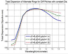
(a)
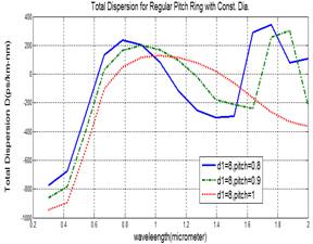
(b)
Fig.4. (a) Dispersion for different pitches with alternate ring hole diameter change (b) Circular hole PCF structure with regular diameter for different pitches (Diameter ‘d’ constant).
IV. RESULTS AND CONCLUSION
In dispersion compensation fibre design large negative dispersion is desirable. Plot of total dispersion as a function of wavelength and after comparing them it is find that for alternate ring air-hole diameter large negative dispersion is -178 (ps/km-nm), for regular diameter it is -202(ps/km-nm), for pitch changes with alternate ring air-hole diameter it is -164 (ps/km-nm),for pitch changes for regular diameter it is -301(ps/km-nm). It is concluded that when small diameter and small pitch is taken then we get large negative dispersion and we can use that particular designs for making of PCF.
[1] Bjarklev A, Broeng J, Bjarklev AS. Photonic crystal fibers. Dordrecht: Kluwer Academic Publishers; 2003.
[2] Knight JC, Birks TA, Russell PSJ, Atkin DM. All-silica singlemode optical fiber with photonic crystal cladding. Opt Lett 1996;21:1547–9.
[3] Broeng J, Mogilevstev D, Barkou SE, Bjarklev A. Photonic crystal fibers: a new class of optical waveguides. Opt Fiber Technol 1999;5:305–30.
[4] Reeves WH, Knight JC, Russell PStJ. Demonstration of ultraflattened dispersion in photonic crystal fibers. Opt Express2002;10:609–13.
[5] T. A. Birks, D. Mogilevtsev, J. C. Knight, and P. St. J. Russell, “Dispersion compensation using single-material fibers,” IEEE Photon. Technol. Lett., vol. 11, pp. 674–676, June 1999.
[6] A. Ferrando, E. Silvestre, J. J. Miret, J. A. Monsoriu, M. V. Andres, and P. St. J. Russell, “Designing a photonic crystal fiber with flattened chromatic dispersion,” Electron. Lett., vol. 35, pp. 325–327, 1999.
[7] M. J. Gander, R. McBride, J. D. C. Jones, D. Mogilevtsev, T. A. Birks, J. C. Knight, and P. St. J. Russell, “Experimental measurement of group velocity dispersion in photonic crystal fiber,” Electron. Lett., vol. 35, pp. 63–64, 1999.
[8] J. K. Ranka, R. S.Windeler, and A. J. Stentz, “Visible continuum generation in air-silica microstructure optical fibers with anomalous dispersion at 800 nm,” Opt. Lett., vol. 25, pp. 25–27, 2000.
[9] W. J. Wadsworth, J. C. Knight, A. Ortigosa-Blanch, J. Arriaga, E. Silvestre, and P. St. J. Russell, “Soliton effects in photonic crystal fibers at 850 nm,” Electron. Lett., vol. 36, pp. 53–55, 2000.