| "ЖУРНАЛ РАДИОЭЛЕКТРОНИКИ" "JOURNAL OF RADIOELECTRONICS" N 9, 1999 |
High Power Converter of Microwaves into DC
Vladimir A. Vanke
Faculty of Physics, Moscow State University
Hiroshi Matsumoto, Naoki Shinohara, Akinori Kita
Radio Atmospheric Science Center, Kyoto University, Japan
Received August 30, 1999
Perspectives of Cyclotron Wave Converter (CWC) of microwaves into DC are discussed in a form of short review. All main parts of CWC (microwave cavity, reverse region and collector) are analyzed. Existing experimental results are briefly described.
1. INTRODUCTION
For many types of wireless power transmission (WPT) systems, diode-type rectenna (rectify antenna) [1,2] is the best (and the simplest) device for back-conversion of microwaves into D.C. Diode-type rectennas have played and play a fundamental role at the stage of principal demonstration of the possibilities of high efficient wireless power transmission by microwaves. However they become not so much attractive for future real high power industrial WPT systems.
Industrial energy systems always demand and use high power and high voltage devices to decrease losses and to increase reliability.
Because of it, we discuss another device allowing to avoid some main negative properties of diode-type rectennas:
·
Low power level of single rectenna element,·
Low output voltage and therefore, necessity to connect diodes in series,·
High level of breakdown possibility being dangerous even at rather small levels of microwave or D.C. overloads.
Some our previous experience in microwave electron beam devices [4-6] enabled us to appreciate the advantages and possibilities of improvement of cyclotron wave converters (CWC) [7-30].
2. PRINCIPLE OF CWC OPERATION
Fig. 1 illustrates the principle of CWC operation. Microwaves at
frequency ![]() induce
transverse electric field in coupler gap of resonant cavity. The resonator is inserted
into external magnetic field
induce
transverse electric field in coupler gap of resonant cavity. The resonator is inserted
into external magnetic field ![]() . Therefore electron beam, which is formed by electron gun and injected
into the resonator, obtains cyclotron rotation at frequency
. Therefore electron beam, which is formed by electron gun and injected
into the resonator, obtains cyclotron rotation at frequency ![]() (a fast cyclotron wave of the electron beam is
exited). The resonant cavity is followed by conversion region
(a fast cyclotron wave of the electron beam is
exited). The resonant cavity is followed by conversion region ![]() , where the external magnetic field is changes
in both the direction and the magnitude.
, where the external magnetic field is changes
in both the direction and the magnitude.
Fig. 1 Scheme of CWC
The longitudinal velocity of rotating electron increases in the divergent magnetic field of the conversion region. Radial component of static magnetic field creates the process when energy of rotation of the electron beam is transferred into the energy of its longitudinal motion. Simultaneously, the electron beam configuration is changed - it takes shape of a spatial helix (energy of fast cyclotron wave is transferred into the energy of synchronous wave of the same polarization).
The accelerated electrons enter collector region, where their kinetic energy is recuperated and transformed into D.C. energy at the load resistance.
High resulting efficiency of CWC is obtained as a result of careful optimization of all main CWC parts. The overall efficiency of CWC can be written as:
|
(1) |
where
![]() - efficiency of
microwave energy transfer from external generator (source) into the energy of electron
beam rotation in resonant cavity,
- efficiency of
microwave energy transfer from external generator (source) into the energy of electron
beam rotation in resonant cavity,
![]() - efficiency of
rotation energy transfer into additional energy of the longitudinal motion inside reversed
magnetic field region,
- efficiency of
rotation energy transfer into additional energy of the longitudinal motion inside reversed
magnetic field region,
![]() - efficiency of
one-stage collector accepting the lowest electron with zero-longitudinal velocity.
- efficiency of
one-stage collector accepting the lowest electron with zero-longitudinal velocity.
3. MICROWAVE CAVITY
The applied energy of microwaves ![]() can be transformed into the energy of electron beam rotation very
effectively. For the main type of oscillations the equivalent scheme of such a microwave
cavity coupler is simple enough and shown in Fig. 2.
can be transformed into the energy of electron beam rotation very
effectively. For the main type of oscillations the equivalent scheme of such a microwave
cavity coupler is simple enough and shown in Fig. 2.
If transit angle of an electron inside the cavity gap is quite large
Fig. 2 Equivalent scheme of microwave coupler
|
(2) |
(where L - length of the gap, vzo - longitudinal velocity of the injected electron beam)
the electron beam conductivities (Fig. 3) are [3]:
|
(3) |
|
|
(4) |
,
where Lc - length of the cavity; L, Le - length and effective length of the cavity gap respectively.
The efficiency of power transformation from external generator into the energy of electron beam rotation
 , , |
(5) |
.
This is a well-known physical result: all power is transmitted from the external generator into the load when their conductivities are matched in a complex-conjugated way, i.e.
(6) |
In this case
 |
(7) |
where: ![]() - Q-factor of
unloaded microwave cavity,
- Q-factor of
unloaded microwave cavity, ![]() - Q-factor of the microwave cavity loaded by external generator
(without electron beam).
- Q-factor of the microwave cavity loaded by external generator
(without electron beam).
The cavity efficiency of 95-98% is quite available.
2. REGION OF REVERSED MAGNETIC FIELD
As a good approximation, the distribution of static magnetic field may be chosen in the following form [15]:
 |
(8) |
 |
(9) |
Where ![]() - parameter of
asymmetry of the reverse. For symmetric reverse:
- parameter of
asymmetry of the reverse. For symmetric reverse: ![]() .
.
The electron beam of a finite cross-section will be accelerated in the longitudinal direction (Fig. 4) inside the reverse region, i.e. beam rotation energy will be transformed into the energy of its longitudinal motion.
One can write for the efficiency:
 , , |
(10) |
where ![]() - transverse
velocity of the beam at the entrance of the reverse region.
- transverse
velocity of the beam at the entrance of the reverse region.
Longitudinal velocity spread (Fig. 4) will be exited because of finite cross-section of the electron beam. One-stage collector must accept (not to reflect) the slowest electron of such beam. Because of it:
 |
(11) |
It is convenient to use the following parameters at the entrance of the reverse region:
 - normalized length
of the reverse region,
- normalized length
of the reverse region,
 - ratio of the
transverse energy to the longitudinal one,
- ratio of the
transverse energy to the longitudinal one,
 - ratio of the beam
radius
- ratio of the beam
radius ![]() to the radius of
cyclotron rotation
to the radius of
cyclotron rotation ![]() of
the beam.
of
the beam.
Fig. 5 Results of computer simulation
The results of the computer simulation [15] for the efficiency ![]() are shown in Fig. 5.
are shown in Fig. 5.
It is important to point out that practically in all cases the optimal configuration of
reversed magnetic field ![]() is asymmetric
is asymmetric ![]() .
.
Coulomb forces are not very essential inside the reverse region if the beam current is
not exceed 0,5-0,75 of the value of Brillouin current ![]() . (See Fig. 6, where
. (See Fig. 6, where ![]() must be found from the
equation
must be found from the
equation ![]() ,
, ![]() - plasma frequency).
- plasma frequency).
The increasing beam displacement inside the reverse region (Fig. 7) must be also taken into account under development.
5. COLLECTOR
Heat rejection and protection against secondary emission are the most important problems of the CWC collector. The potential of collector surface is much lower then the potential of CWC microwave cavity. Such electric field will stimulate the back-motion of the secondary electrons.
To solve this problem it is necessary to use a special secondary emission protecting coating of the collector surface. Besides, the additional electrode (Fig. 1,8,9) can be effectively used to create a local electric field protecting against back-motion of the secondary electrons.
The formal computer simulation of the collector area [17] is practically the same as for another microwave conventional devices (Klystrons, TWTs, etc.) with collector of a depressed potential (Fig. 8).
At normal operational mode practically all beam current reaches the collector surface (Fig. 9). A small current of primary (and maybe secondary) electrons forms
(by ![]() ) a negative
potential of the additional electrode of collector region.
) a negative
potential of the additional electrode of collector region.
If input signal is smaller or larger than the normal one a part of beam current is
intercepted by the cavity. Using R0 >> R we can solve the problem
of CWC protecting against microwave or D.C. overload.
PRELIMINARY EXPERIMENTS
The first CWC experiment by D.C.Watson, R.W.Grow and C.C.Johnson was carried out at power level of 1-1.5 W [7-9], i.e. like power level of a single diode-type rectenna element. The efficiency of 56% has been achieved.
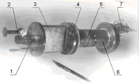
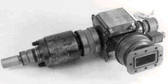
At Moscow State University a version of CWC was also tested (Fig. 13). The efficiency of 70-74% at power level of 25-35 Watts was demonstrated (Fig. 14).
Fig. 13 1 - MW input, 2 - electron gun, 3 - microwave cavity, 4 - a part of magnet system, 5 - isolator, 6 - collector, 7 - pump
The Tory Research and Production Corp. (V.K.Rosnovsky, K.I.Sigorin and colleagues) in collaboration with Moscow State University created and tested several high power CWC, Fig. 15. The efficiency of 60-70% up to 83% have been demonstrated at microwave power level of 10 kW and output D.C. voltage of 15-20 kV.
Fig. 15 High Power CWC of Tory Corp.
The Istok State Research and Production Corp. (Yu.A.Budzinsky, S.V.Bykovsky and colleagues) started in the development of CWC. An intermediate version of CWC (Fig. 16, Fig. 17) was shown at WPT’95 Int. Conference in Kobe (Japan).
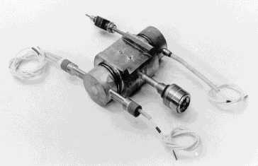 Fig. 16 |
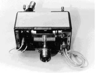 Fig. 17 |
Preliminary version of CWC of Istok Corp,
7. DISCUSSION
In conclusion, using existing theoretical and experimental results it should be summarized the optimal parameters of CWC:
Output power range, kW 0.5 ... 50
Conversion efficiency, %
possible
85 ... 90
demonstrated up to
83
Output voltage range, kV 1 ... 50
Frequency range, GHz 1...10
Bandwidth, %
0.5 ... 5
Focusing system
permanent magnet
The main advantages of CWC are:
· High conversion efficiency |
· No breakdown problems |
· High power level |
· High reliability |
| · High output voltage | · No higher harmonic re-radiation problems |
Existing preliminary experiments performed at the frequency of 2.45 GHz have confirmed the main physical ideas of CWC. Nevertheless, the real CWC-devicesacceptable for microwave energy transmission systems must be developed yet.
CWC may be preferable in different types of Microwave Power Transmission Systems (MPTS), including future Space Power Satellites (SPS) and ground-based MPTS (Fig. 10-12). Some types of mirror concentrators will be necessary to use CWC effectively.
CWC is a new device of microwave power conversion into D.C. The motivation of developing the CWC was originally to invent an efficient power converter on a ground receiving site for the Solar Power Satellite (SPS). However is also applicable to many other occasions where microwave power transmissions of high density of electric power is necessary, such as non contact wireless power transmission in factories and for power feeding to electric vehicles.
REFERENCES
[1] W.C.Brown, ‘History of Power Transmission by Radio Waves,’ IEEE Transaction on Microwave Theory and Techniques, vol. MTT-32, no. 9, 1984, pp. 1230-1242.
[2] W.C.Brown, ‘The Early History of Wireless Power Transmission,’ Proc. of The Forth Int. Symposium -SPS’97: Energy and Space for Humanity and The Third Int. Conference on Wireless Power Transmission, Montreal, August 24-28, 1997, pp. 177-186.
[3] C.L.Cuccia, ‘The Electron Coupler - a Developmental Tube for Amplitude Modulation and Power Control at UHF,’ RCA Rev., vol. 10, no. 2, 1949, p. 270.
[4] V.A.Vanke, ‘Cyclotron Wave Parametric Amplifiers,’ Candidate of Sciences (Phys. & Math.) thesis (Ph.D. thesis), Moscow State University, 1967.
[5] V.A.Vanke, V.M.Lopukhin, V.L.Savvin, ‘Super Low Noise Cyclotron Wave Amplifiers,’ Sov. Phys. Usp., vol. 99, 1969, pp. 743-756
[6] V.A.Vanke, ‘Interaction of Transverse Oscillations and Waves in the Electron Beams and Electromagnetic Fields,’ Doctor of Sciences (Phys. & Math.) thesis, Moscow State University, 1981.
[7] D.C.Watson, R.W.Grow, C.C.Johnson, ‘A Rectifier with Transverse Interaction,’ Microwave Power Engineering (edited by Okress E. C.) , vol. 1, 1968, Academic Press, New York and London, pp. 408-419 (Russian Edition).
[8] D.C.Watson, K.T.Tabbot, C.C.Johnson, ‘A Cyclotron Wave Microwave Power Converter,’ Proc. IEEE, 1966, no. 11, p. 1797
[9] D.C.Watson, R.W.Grow, C.C.Johnson, ‘A Cyclotron Wave Rectifier for S-Band and X-Band,’ J. Microwave Power, 1970, vol. 5, no. 2, p. 72
[10] V.A.Vanke, V.L.Savvin, ‘Electron Beam Transverse Wave Transformation in Axial-Symmetrical Fields,’ Radiotechnique & Electronics, 1970, vol. 15, no. 11, p. 2408. (in Russian).
[11] V.A.Bardenkov, V.A.Vanke, I.S.Gorshkov, V.M. Lopukhin, ‘Microwave Power Converter with Reversed Magnetic Field,’ Radiotechnique & Electronics, 1976, vol. 21, no. 4, p. 821. (in Russian)
[12] V.A.Vanke, A.M.Khapaev, ‘Mathematical Simulation and Parameter Optimization of Synchronous Wave Devices,’ Processing and Interpretation of Experiments, MSU Edition, 1976, issue 4, p. 148, (in Russian)
[13] V.A.Bardenkov, V.A.Vanke, V.L.Savvin, ‘Power-Capacity of the Electron Beam in Microwave Resonator with Transverse Electric Field,’ Radiotechnique & Electronics, 1977, vol. 22, no. 4, p. 863. (in Russian).
[14] V.A.Vanke, V.M.Lopukhin, V.L.Savvin, ‘Problems of Space Solar Power Stations,’ Sov. Phys. Usp, 1977, vol. 123, no. 4, p. 633. (in Russian).
[15] V.A.Vanke, A.A.Zaytsev, V.M.Lopukhin, V.L.Savvin, ‘An Analysis of Physical Phenomenas in the Reverse Region of Cyclotron Energy Converter,’ Radiotechnique & Electronics, 1978, vol. 23, no. 6, p. 1217. (in Russian).
[16] V.A.Vanke, V.M.Lopukhin, V.K.Rosnovsky, V.L.Savvin, K.I.Sigorin, ‘Perspectives of Application of High- Efficiency Microwave into D.C. Converters at Energy Transmission from Space for Use on Earth,’ Proc. of the 15th Annual Tziolkovsky Reading Conference, Vol. ‘Space Industry’, IIET Edition, Ac.Sc., 1981, p. 102. (in Russian).
[17] I.M.Bleyvas., V.A.Vanke, L.M.Rybnikova, V.L.Savvin, ‘Numerical Simulation of Recuperation Processes for Cyclotron Converter,’ Radiotechnique & Electronics, 1982, vol. 27, no. 5, p. 1009. (in Russian).
[18] V.A.Vanke, V.M.Lopukhin, V.K.Rosnovsky, V.L.Savvin, K.I.Sigorin, ’Ground-Based Receiving/Converting System for Space Solar Power Systems,’ Radiotechnique & Electronics, 1982, vol. 27, no. 5, p. 1014. (in Russian).
[19] V.A.Vanke, V.I.Gorelikov, V.L.Savvin, ‘Fast Cyclotron Waves Excitation in High Power Electron Beam of Cyclotron Energy Converter,’ Electron Technique, Vol. Microwave Electronics, 1983, issue no. 3(351), p. 7. (in Russian).
[20] V.A.Vanke, V.I.Gorelikov, V.L.Savvin, ‘Space Charge Forces Influence on Energy Exchanging Processes in Microwave Cavity of Cyclotron Converter,’ Electron Technique, Vol. Microwave Electronics, 1984, issue no. 8(368), p. 11. (in Russian).
[21] V.A.Vanke, V.L.Savvin, ‘Cyclotron Wave Converter for SPS Energy Transmission System,’ Proc. of Sec. Intern. Symp. Power from Space ( SPS’91), Paris, August 27-30, 1991, pp. 515-520.
[22] V.A.Vanke, V.L.Savvin, ‘Cyclotron Wave Converter for Wireless Power Transmission in X and K Bands,’ Proc. of the 29th. Microwave Power Symp., Chicago, July 25-27, 1994, pp. 74-75.
[23] V.A.Vanke, A.V.Rachnikov, S.K.Lesota, V.L.Savvin, ’An Investigation on Space Power Beaming by Microwaves in Moscow University,’ Proc. of the 29th. Microwave Power Symp., Chicago, July 25-27, 1994, pp. 114-115.
[24] B.A.Osadin, V.A.Vanke, ‘WPT Electron Beam Devices,’ SPS/WPT Reunion Island workshop, Dec. 13-16, 1994. See: SPS 2000 News Letter, no. 11, March 1995, p. 10. (ISAS Edition, Japan).
[25] V.A.Vanke, ‘Cyclotron Wave Converter,’ Proceedings of the Medium Term Case Studies Workshop Wireless Power Transportation, Reunion Island --1, December 13-16, 1994, SOFIOM-Reunion, pp. 10.1-10.8.
[26] V.A.Vanke, V.L.Savvin, I.A.Boudzinski, S.V.Bykovski, ‘Development of Cyclotron-Wave Converter,’ Abstracts of The Second International Wireless Power Transmission Conference WPT'95, 16-19 October, Kobe, Japan, p.3-3.
[27] V.A.Vanke, A.V.Rachnikov, V.L.Savvin, ‘On Some Issues of Wireless Power Transmission Systems,’ Abstracts of The Second International Wireless Power Transmission Conference WPT'95, October 16-19, 1995, Kobe, Japan, p.6-3.
[28] V.A.Vanke, V.L.Savvin, ‘On Some Microwave Physics Research at Moscow State University and Russian Industries,’ (Plenary Talk), 23rd IEEE Int. Conference on Plasma Science ICOBS’96), Boston, June 3-5, 1996. Abstracts, pp. 62, 226.
[29] V.A.Vanke, V.L.Savvin, ‘Non-Traditional Microwaves Tubes Based on Electron Beam Cyclotron and Synchronous Waves Using. Status & Perspective,’ (Invited Presentation), ESA/NATO Workshop on TWTA, April 7-10, 1997, Noordwijk, Netherlands.
[30] V.A.Vanke, H. Matsumoto, N. Shinohara, A. Kita, Cyclotron Wave Converter of Microwaves into DC, IEICE Trans. on Electronics (Japan), 1998, vol. E81-C, pp. 1136-1142.
Authors: Vladimir. A. Vanke, e-mail: vanke@mesps.phys.msu.su,
Hiroshi
Matsumoto,
Naoki
Shinohara,
Akinori
Kita